Combined harvester conveying trough with forward rotation conveying function and reverse rotation grass discharge function

A technology for combine harvesters and conveying troughs, which is applied to harvesters, cutters, agricultural machinery and implements, etc. It can solve the problems of complex structure and increased probability of failure, so as to simplify the transmission system, improve efficiency and safety , the effect of simple structure

Active Publication Date: 2016-11-09
JIANGSU UNIV
View PDF8 Cites 7 Cited by
  • Summary
  • Abstract
  • Description
  • Claims
  • Application Information

AI Technical Summary

Problems solved by technology

[0002] Most of the conveying troughs of the existing domestic and foreign combine harvesters with the function of forward-rotating grass feeding and reverse-reversing grass-removing are provided with a forward clutch and a reverse clutch on the transmission input shaft, for example, the invention patent of application number 201110037073.4 (combined harvester) A bevel gear transmission box is designed, and the box input shaft is protruded on the left and right sides of the transmission box. The direction of the two box input shafts is opposite. The box input shaft in the reverse direction is linked with the harvesting input shaft to transmit the driving force in the forward and reverse directions, realizing the function of the combine harvester conveying trough forwardly rotating grass to transport grass and reversely returning grass, but the arrangement of two power transmission routes makes The structure is more complex, the forward and reverse clutches and the input shafts of the forward and reverse boxes work alter...

Method used


Image

  • Combined harvester conveying trough with forward rotation conveying function and reverse rotation grass discharge function
  • Combined harvester conveying trough with forward rotation conveying function and reverse rotation grass discharge function
  • Combined harvester conveying trough with forward rotation conveying function and reverse rotation grass discharge function

Examples


Embodiment Construction

[0032]The specific implementation manners of the present invention will be described in further detail below in conjunction with the accompanying drawings.

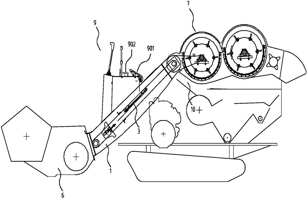
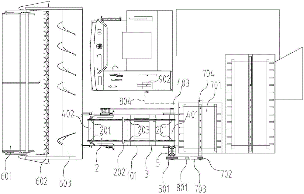
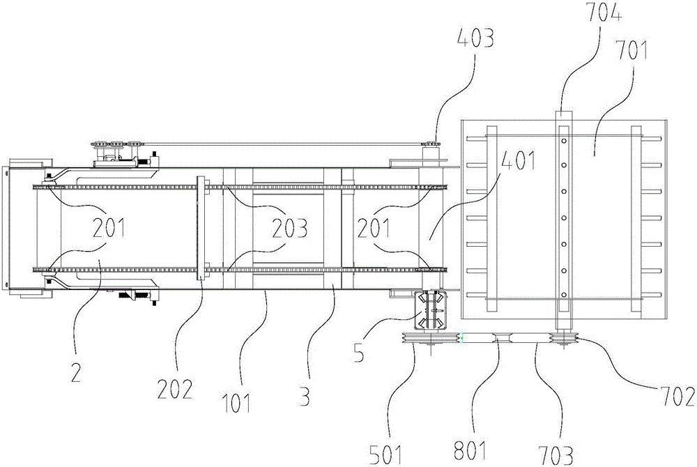
[0033] Such as Figure 1~3 As shown, a combine harvester conveying trough with the function of forward-rotating conveying and reverse-reversing grass removal includes a conveying trough housing 1, a chain rake 2, a supporting plate 3, a transmission and tension 4; the conveying trough housing 1 The input end is connected to the feeding port of the combine harvester header feeding device 6, and the output end is connected to the feeding port of the combine harvester threshing device 7; the chain rake 2 includes a power input shaft 401 and a power output shaft arranged on the conveying trough The conveying sprocket 201 on the 402, the conveying sprocket 201 is meshed with the circular conveying chain 203 with rake teeth 202, and the rake teeth 202 are evenly distributed on the conveying chain 203; The middle of the conveyi...


PUM

PropertyMeasurementUnit
Total lengthaaaaaaaaaa

Abstract

The invention provides a combined harvester conveying trough with a forward rotation conveying function and a reverse rotation grass discharge function. The conveying trough comprises a conveying trough shell, a chain harrow, a supporting plate, a transmission mechanism and a tensioning mechanism. By means of a tension wheel mechanism, power between a power output shaft of a combined harvester threshing cylinder and a power input shaft of the conveying trough is cut and connected, the power is transmitted in the mode that a bevel gear in a forward rotation transmission box and a bevel gear in a reverse rotation transmission box are always meshed, reversing operation of power connection shafts in the forward rotation transmission box and in the reverse rotation transmission box is controlled in the mode that a driver pulls a handle on a driving console, a transmission system of the forward rotation and reverse rotation conveying trough of a combined harvester is simplified, the grass blocking problem in the conveying trough can be quickly solved, and obstacle removal difficulty of grass blocking of the conveying trough in the combined harvester during harvesting is reduced. The conveying trough is simple in structure, convenient to operate and capable of greatly improving efficiency and safety when applied to the combined harvester.

Description

technical field [0001] The invention relates to the technical field of a rice and wheat conveying trough device on a combine harvester, in particular to a combine harvester conveying trough with the function of forward rotation, reverse rotation and reverse weed removal, which can be widely used in high-performance harvesting of rice and wheat. Background technique [0002] Most of the conveying troughs of the existing domestic and foreign combine harvesters with the function of forward-rotating grass feeding and reverse-reversing grass-removing are provided with a forward clutch and a reverse clutch on the transmission input shaft, for example, the invention patent of application number 201110037073.4 (combined harvester) A bevel gear transmission box is designed, and the box input shaft is protruded on the left and right sides of the transmission box. The direction of the two box input shafts is opposite. The box input shaft in the reverse direction is linked with the harv...

Claims


Application Information

Patent Timeline
IPC IPC(8): A01D41/12A01F12/46
CPCA01D41/12A01F12/46
Inventor 李耀明杨亚男陈郁唐忠
Owner JIANGSU UNIV
Why Eureka
Try Eureka