An upper cover assembly and cooking utensils thereof
A cover component and component technology, which is applied in the direction of cooking utensil lids, cooking utensils, kitchen utensils, etc., can solve the problems of narrowing of the compression line gap of the valve body, heat loss of cooking utensils, energy loss, etc., to achieve convenient use and improve user experience , the effect of simple structure
- Summary
- Abstract
- Description
- Claims
- Application Information
AI Technical Summary
Problems solved by technology
Method used
Image

Examples
Embodiment 1
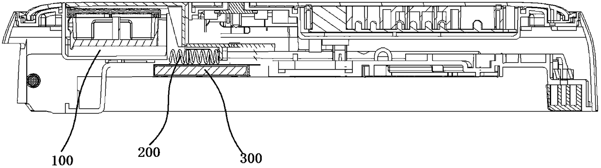
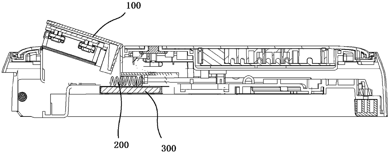
[0039] refer to image 3 and Figure 4 In this embodiment, the exhaust gas of the overall structure of the steam valve assembly is mainly described. Specifically, the steam valve assembly is driven by the drive assembly in the first state (such as image 3 described) and the second state (such as Figure 4 described) movement between.
[0040] The first state and the second state are used to determine the first state and the second state by detecting the amount of steam that the steam valve assembly instantaneously discharges to the outside, that is, the amount of steam that is instantaneously discharged to the outside in the second state is greater than that in the first state. The amount of steam exhausted from the outside; the preferred first state usually refers to the state when the steam valve assembly does not start to exhaust, and the second state refers to the state when the steam valve assembly is exhausted (including fully exhausted state and partial exhausted sta...
Embodiment 2
[0051] refer to Figure 9 As shown, the main difference between the second embodiment and the first embodiment is that the opening or closing of the air inlet 130 or the air outlet of the steam valve assembly 100 is mainly controlled by the drive assembly 200 through the communication plate 210, and then the exhaust of the steam valve is controlled. quantity.
[0052] Specifically, as in Embodiment 1, the steam valve assembly 100 includes a valve body 110, a steam channel 120 disposed in the valve body, one end of the steam channel is connected to an air inlet 130, and the other end is connected to an air outlet 140, and the driving assembly 200 For controlling the opening or closing state of the air inlet or the air outlet, the driving assembly 200 may adopt a temperature-sensitive elastic member as disclosed in Embodiment 1.
Embodiment 3
[0054] refer to Figure 10 As shown, the main difference between the third embodiment and the first embodiment is that in this embodiment, the description is mainly on the action and exhaust of the partial structure of the steam valve assembly 100 , and the valve cover 150 is preferred for the partial structure in this embodiment.
[0055] The steam valve assembly 100 includes a valve body 110 and a valve cover 150 movably assembled on the valve body. In addition, the upper cover assembly also includes a lining cover 500 and a face cover 600, wherein a cavity for placing the steam valve assembly 100 is formed in the lining cover 500. cavity, the bonnet 150 and the face cover 600 belong to different components, that is, the bonnet 150 does not follow the overall movement of the valve body, and the driving assembly 200 moves to drive the valve Lifting the valve cover 150 is used for exhausting, that is, the stretched drive assembly only exerts force on the valve cover 150 , and ...
PUM
 Abstract
Description
Claims
Application Information
 - Generate Ideas
- Intellectual Property
- Life Sciences
- Materials
- Tech Scout
- Unparalleled Data Quality
- Higher Quality Content
- 60% Fewer Hallucinations
Browse by: Latest US Patents, China's latest patents, Technical Efficacy Thesaurus, Application Domain, Technology Topic, Popular Technical Reports.
© 2025 PatSnap. All rights reserved.Legal|Privacy policy|Modern Slavery Act Transparency Statement|Sitemap|About US| Contact US: help@patsnap.com