
A fast hot melt glue gun

A hot-melt glue gun and fast technology, which is applied to devices and coatings that apply liquid to the surface, can solve the problems of low heating efficiency, affecting rapid glue dispensing, poor thermal conductivity of insulating films, etc. Direct heating effect and high heating efficiency

Active Publication Date: 2018-11-09
NINGBO HANPU TOOLS
View PDF9 Cites 0 Cited by
  • Summary
  • Abstract
  • Description
  • Claims
  • Application Information

AI Technical Summary

Problems solved by technology

[0003] In order to solve the above problems, the PTC heating module is often used instead of the heating plate to heat the hot-melt rubber hose. The power supply device of the PTC heating module can use a portable power supply device such as a lithium battery power supply device, so the limitation of the place of use is small; however, The existing PTC heating module directly connects the positive and negative poles of the power module to both sides of the PTC ceramic heating sheet, so an insulating layer needs to be provided between the PTC ceramic heating sheet and the conductive heating head made of metal for insulation protection. The usual practice is to wrap a layer of insulating film on the outside of the PTC ceramic heating sheet. The thermal conductivity of the insulating film is poor, so the heating efficiency is not high; after the existing hot melt glue gun is used, the glue after melting often flows back. And overflow phenomenon, after cooling, these overflowing colloids will re-solidify and make the glue stick thicker. When used again, the glue stick cannot be pushed into the heating head smoothly, and it takes longer heating time or the glue stick needs to be taken out and cleaned before continuing Use will affect the quick glue release and cause inconvenience in use

Method used


Image

  • A fast hot melt glue gun
  • A fast hot melt glue gun
  • A fast hot melt glue gun

Examples


Embodiment 1

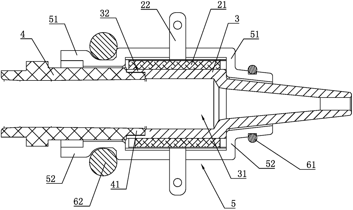
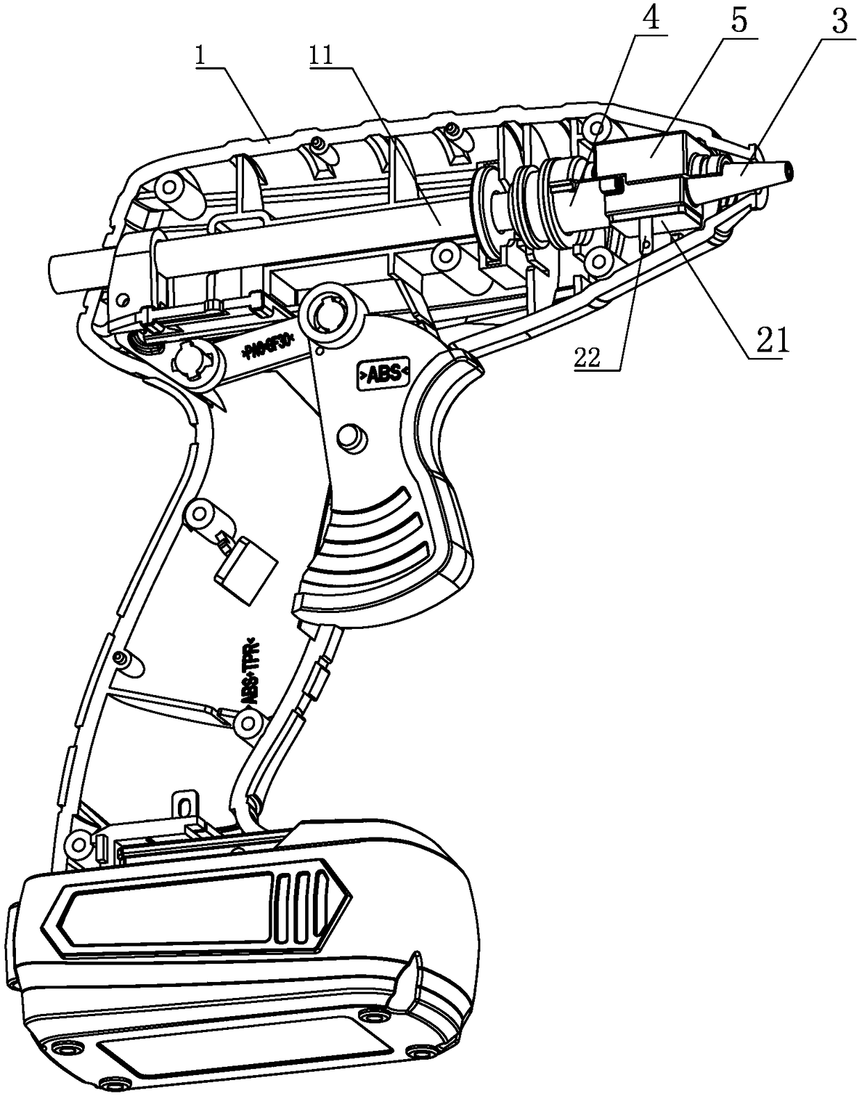
[0018] Embodiment 1: A fast hot-melt glue gun, including a gun body 1, a glue stick 11, a hot-melt device and a power module (not shown in the figure) are arranged in the gun body 1, and the hot-melt device includes a PTC ceramic heating sheet 21, Negative connecting piece 22 and conductive heating head 3, the conductive heating head 3 is provided with a thermal melting cavity 31, the PTC ceramic heating chip 21 is arranged outside the thermal melting cavity 31 and the inner side of the PTC ceramic heating chip 21 is close to the conductive heating head 3 On the top, the PTC ceramic heating piece 21 is electrically connected to the negative input end of the power module through the negative connecting piece 22, the conductive heating head 3 is electrically connected to the positive input end of the power module, and the rear end of the conductive heating head 3 is provided with a leak-proof rubber sleeve 4 , the rear end of the conductive heating head 3 is provided with a conne...

Embodiment 2

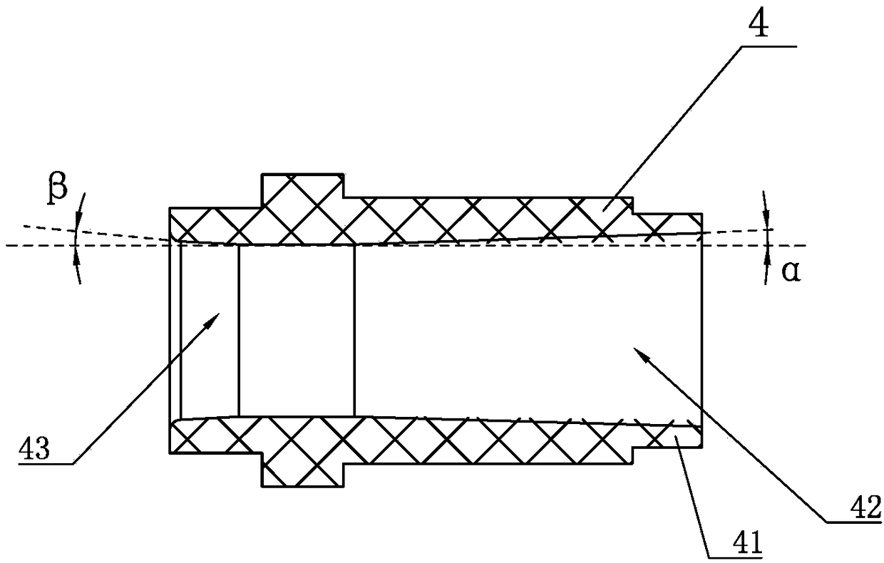
[0019] Embodiment 2: The remaining parts are the same as Embodiment 1, the difference is that a heat-insulating bushing 5 is arranged around the outside of the conductive heating head 3, and the PTC ceramic heating sheet 21 is located between the heat-insulating bushing 5 and the conductive heating head 3 , There are two PTC ceramic heating chips 21, and the two PTC ceramic heating chips 21 are symmetrically arranged on both sides of the conductive heating head 3, and the inclination angle α of the inner surface of the first tapered through hole 42 is 0.8°. Wherein, the heat-insulating bushing 5 is made of high-temperature-resistant and non-conductive material, which can play a role of heat insulation, reduce heat loss, and ensure the heating effect. In this embodiment, the thermal insulation bushing 5 can be made of PA66 (polyamide 66, polyamide 66 or nylon 66) material.

Embodiment 3

[0020] Embodiment 3: the rest is the same as Embodiment 1, the difference is that the heat insulation bushing 5 includes a first heat insulation half shell 51 and a second heat insulation half shell 52 arranged symmetrically, surrounding the first heat insulation half shell A first clip 61 and a second clip 62 are clamped on the outer sides of the shell 51 and the second heat-insulating half-shell 52 , and the inclination angle α of the inner surface of the first tapered through hole 42 is 3°.

[0021] In the first to third embodiments above, if the inclination angle α of the inner surface of the first tapered through hole 42 is unreasonably set, the melted colloid will easily accumulate in the middle of the leak-proof rubber sleeve 4 to form an arch or other shapes, so that Glue stick 11 can not extrude smoothly when using again.


PUM

PropertyMeasurementUnit
angleaaaaaaaaaa
angleaaaaaaaaaa

Abstract

The invention discloses a quick hot melt glue gun. The quick hot melt glue gun comprises a gun body; and a glue rod, a hot melt device and a power supply module are arranged in the gun body. The quick hot melt glue gun is characterized in that the hot melt device includes at least one PTC ceramic heating piece, a negative pole connecting piece and an electric conduction heating head; a hot melt cavity is formed in the electric conduction heating head; the PTC ceramic heating piece is arranged out of the hot melt cavity, and the inner side of the PTC ceramic heating piece is tightly bonded on the electric conduction heating head; the PTC ceramic heating piece is electrically connected with a negative pole input end of the power supply module through the negative pole connecting piece; the electric conduction heating head is electrically connected with a positive pole input end of the power supply module; a leakage preventing rubber sleeve is arranged at the back end of the electric conduction heating head; a connecting concave cavity is formed in the back end of the electric conduction heating head; a connecting convex ring is arranged at the front end of the leakage preventing rubber sleeve, and extends into the connecting concave cavity; and a first conical through hole is formed in the front end of the leakage preventing rubber sleeve. The quick hot melt glue gun has the advantages of more direct heating effect and higher heating efficiency; and the glue rod can be smoothly extruded out in reuse, so that the use is convenient and fast.

Description

technical field [0001] The invention relates to a glue gun device, in particular to a fast hot melt glue gun. Background technique [0002] The hot melt glue gun is a manual melt glue extruding tool. The heating device in the existing hot melt glue gun generally uses alternating current to supply power to the heating plate, thereby heating the melt pipe to melt the glue, so it needs to be near the AC power supply There are certain restrictions on where to use for operations. [0003] In order to solve the above problems, the PTC heating module is often used instead of the heating plate to heat the hot-melt rubber hose. The power supply device of the PTC heating module can use a portable power supply device such as a lithium battery power supply device, so the limitation of the place of use is small; however, The existing PTC heating module directly connects the positive and negative poles of the power module to both sides of the PTC ceramic heating sheet, so an insulating l...

Claims


Application Information

Patent Timeline
Patent Type & Authority Patents(China)
IPC IPC(8): B05C5/04
CPCB05C5/001
Inventor 陈会甫
Owner NINGBO HANPU TOOLS
Learn More