Punching and riveting device

A technology of riveting and punching, which is applied in the field of auxiliary devices, can solve problems such as fracture, and achieve the effect of solving the problem of easy fracture

Active Publication Date: 2016-11-09
CHINA HANGFA SOUTH IND CO LTD
View PDF4 Cites 2 Cited by
  • Summary
  • Abstract
  • Description
  • Claims
  • Application Information

AI Technical Summary

Problems solved by technology

[0003] The invention provides a punching riveting device to solve the existing te

Method used


Image

  • Punching and riveting device
  • Punching and riveting device
  • Punching and riveting device

Examples


Example Embodiment

[0028] The embodiments of the present invention will be described in detail below with reference to the accompanying drawings, but the present invention can be implemented in many different ways defined and covered by the claims.

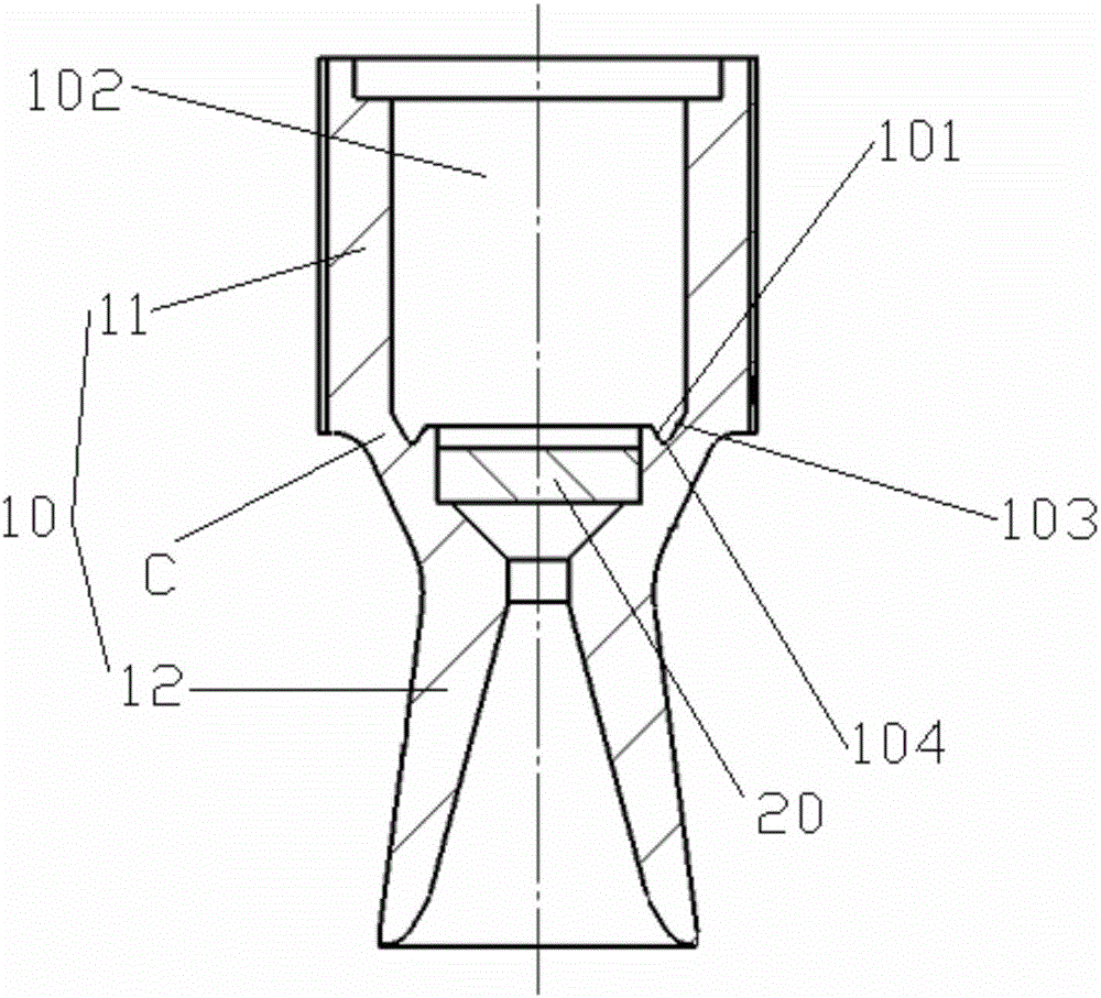
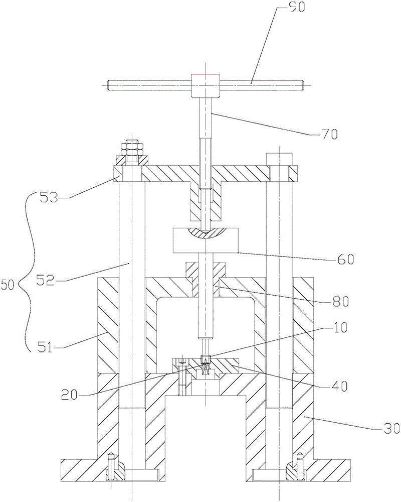
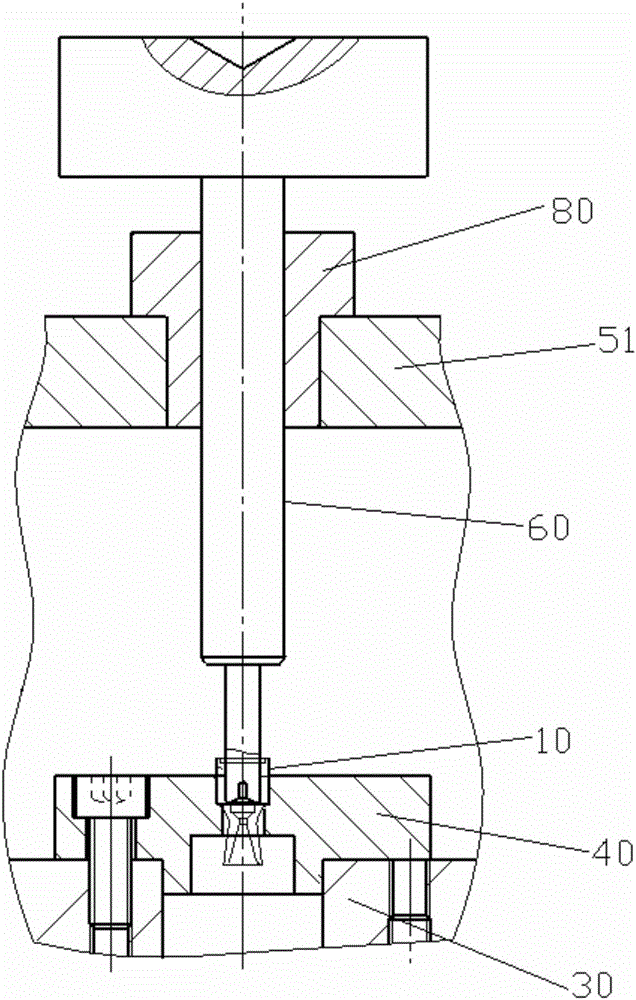
[0029] Reference figure 1 , figure 2 , Figure 5 with Image 6 , The preferred embodiment of the present invention provides a punching riveting device for punching and riveting the first outer cone surface 101 of the inner frustum of the first part 10 so as to be installed on the first part 10 The second part 20 and the first part 10 in a mounting channel 102 are assembled into one body, and the riveting device includes: a support seat 30 arranged on the operating platform, and the support seat 30 is provided with a device for installing the first part 10 The clamp body 40, the first part 10 is vertically installed on the clamp body 40 and the top end thereof extends to the outside of the clamp body 40; the mounting bracket 50 is arranged on the suppor...


PUM


Abstract

The invention discloses a punching and riveting device. The punching and riveting device comprises a support base arranged on an operation platform, a mounting bracket arranged on the support base and a plurality of punches, wherein a clamp body used for mounting a first part is arranged on the support base; the punches used for propping and jacking a first outer conical face to apply a riveting force to the first outer conical face so as to fasten a second part into a first mounting channel are arranged on the mounting bracket, the tops of the punches are connected with a force application bar which drives the corresponding punch to move downwards to prop and jack the first outer conical face so as to apply a riveting force to the first outer conical face, and the force application bar is vertically arranged on the mounting bracket; a first inner conical face for propping against the first outer conical face is formed on the bottom end surface of each punch, the inner taper angles of the first inner conical faces of the punches are different, and the punches are sequentially connected with the force application bar from the small inner taper angles to the big inner taper angles to realize riveting processing of the first outer conical face, so that the first outer conical face is gradually deformed to fasten the second part into the first mounting channel.

Description

technical field [0001] The invention relates to the field of auxiliary devices, in particular to a punching riveting device. Background technique [0002] like figure 1 As shown, the first part 10 is provided with a vertical and through-through first installation channel 102, and the inner wall of the first installation channel 102 is provided with a tapered first outer cone surface 101, and the first installation channel 102 is installed There is a second part 20 . By applying riveting force to the first outer tapered surface 101 , the second part 20 and the first part 10 are assembled into one body. During the riveting process, the part C where the first outer tapered surface 101 is processed on the first part 10 is prone to breakage, and the first outer tapered surface 101 after punching and riveting is not smooth and flat. Contents of the invention [0003] The invention provides a punching riveting device to solve the existing technical problem that the first part ...

Claims


Application Information

Patent Timeline
IPC IPC(8): B21D39/00B21D43/00B21D37/00
CPCB21D37/00B21D39/00B21D43/003
Inventor 张雅琼贺冶张菊绒徐舟叶才铭赵强
Owner CHINA HANGFA SOUTH IND CO LTD
Why Eureka
Try Eureka