Supercharge Your Innovation With Domain-Expert AI Agents!

Combined-type emergency power repair vehicle

An electric emergency repair vehicle and combined technology, which is applied in the direction of motor vehicles, goods transport vehicles, and vehicles used for freight transportation, can solve the problems of affecting the process and speed of electric power operations, untimely adjustment, and inconvenient rotation, etc., so as to reduce adjustments Time and adjust the difficulty, prevent safety hazards, increase the effect of safety

Active Publication Date: 2016-11-09
玉环诚和工业设计有限公司
View PDF6 Cites 0 Cited by
  • Summary
  • Abstract
  • Description
  • Claims
  • Application Information

AI Technical Summary

Problems solved by technology

[0002] At present, with the development of the times and the advancement of science and technology, people's living standards are getting higher and higher, and people's requirements for power repair and maintenance are getting higher and higher. In the existing technology, the components of the power system Sometimes it is necessary for the power maintenance organization to send out the electric emergency repair vehicle in time for repair and maintenance. However, in the existing electric emergency repair vehicle, the rotation of the raised part is inconvenient, and it is not timely to perform small local adjustments. When these situations are serious, It will affect the process and speed of electric power work and bring inconvenience to the people, so we need a new type of electric power repair vehicle to solve the problems encountered at this stage

Method used


Image

  • Combined-type emergency power repair vehicle
  • Combined-type emergency power repair vehicle
  • Combined-type emergency power repair vehicle

Examples


Embodiment 2

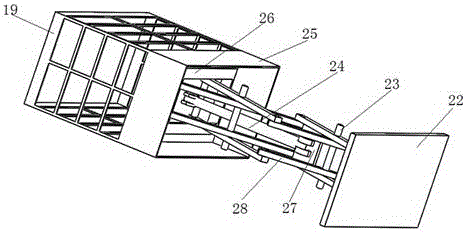
[0021] In this embodiment, on the basis of Embodiment 1, further, the bottom surface of the workbench bottom plate 30 is provided with a vertical ladder upper plate 26 near the edges of both sides; the lower side of the workbench bottom plate 30 is provided with a supporting hydraulic pressure Shaft 24; the bottom end of the supporting hydraulic shaft 24 is connected with a hydraulic rod support plate 27; the lower side of the upper plate 26 of the vertical ladder is provided with a group of support bars 28; The position of supporting shaft 23 is provided with; The bottom of described lower supporting bar 28 is connected with vertical ladder bottom plate 29; The bottom surface of described vertical ladder bottom plate 29 is connected with workbench base plate 22; The two sides are respectively connected with the inner side of the chassis 16 and the rear plate 6 .

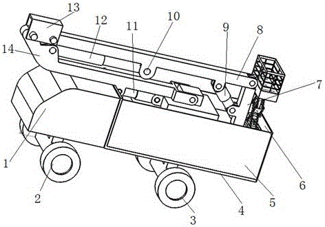
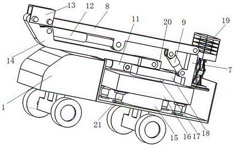
[0022] When the present invention is implemented, the chassis rotating shaft 15 is installed below the chassis 16...


PUM


Abstract

The invention discloses a combined-type emergency power repair vehicle which comprises a vehicle head, wherein a baseplate is installed on the bottom face of a side plate; hydraulic struts are disposed on the top face of the baseplate near four corners; a chassis rotation shaft is installed at the center of the top face of the baseplate; the other end of the chassis rotation shaft is connected to a chassis; a box body rotation shaft is connected to the top face of the chassis; the other end of the box body rotation shaft is connected to a box body; an adjustment arm is disposed on the rear side of the box body; one end of the adjustment arm is connected to a second-level arm; a connecting arm table is installed on the top face of the box body; a first-level hydraulic rod is connected to the front side face of the box body; a supporting rotation shaft is disposed at the center of the bottom face of the second-level arm; a second-level hydraulic rod is connected to one side of the supporting rotation shaft; two side faces of the connecting arm table are connected to one end of a first-level arm; a connecting hood is disposed on the other end of the first-level arm; and a working table guardrail is disposed on the upper part of the rear side of the adjustment arm. The vehicle disclosed by the invention has the advantages that the rotatable chassis and a vertical ladder are adopted; operations are convenient; and working efficiency is increased.

Description

technical field [0001] The invention relates to the technical field of electric power maintenance equipment, in particular to a combined electric emergency repair vehicle. Background technique [0002] At present, with the development of the times and the advancement of science and technology, people's living standards are getting higher and higher, and people's requirements for power repair and maintenance are getting higher and higher. In the existing technology, the components of the power system Sometimes it is necessary for the power maintenance organization to send out the electric emergency repair vehicle in time for repair and maintenance. However, in the existing electric emergency repair vehicle, the rotation of the raised part is inconvenient, and it is not timely to perform small local adjustments. When these situations are serious, It will affect the process and speed of electric power work, and bring inconvenience to the people, so we need a new type of electri...

Claims


Application Information

Patent Timeline
Patent Type & Authority Applications(China)
IPC IPC(8): B60P3/00B60P1/02
CPCB60P1/02B60P3/00
Inventor 何建忠张毅王金涛李肖伟孟涵韩温喜赵鹏王世峰吴福春
Owner 玉环诚和工业设计有限公司
Features
  • R&D
  • Intellectual Property
  • Life Sciences
  • Materials
  • Tech Scout
  • Unparalleled Data Quality
  • Higher Quality Content
  • 60% Fewer Hallucinations
Learn More