
An automatic vibrating feeding tray for metal short tubes

A technology of vibrating feeding and short tube, applied in the direction of conveyor, conveyor objects, transportation and packaging, etc., can solve the problems of fast processing speed and slow feeding speed of metal short tube, and achieve the speed of supplying and feeding. Effect

Active Publication Date: 2018-07-06
PINGHU PINYAO MACHINERY AUTOMATION CO LTD
View PDF4 Cites 0 Cited by
  • Summary
  • Abstract
  • Description
  • Claims
  • Application Information

AI Technical Summary

Problems solved by technology

At present, there is no vibrating plate for it. In addition, the processing speed of the short metal tube is relatively fast, and the current feeding speed of the vibrating plate is relatively slow.

Method used


Image

  • An automatic vibrating feeding tray for metal short tubes
  • An automatic vibrating feeding tray for metal short tubes
  • An automatic vibrating feeding tray for metal short tubes

Examples


Embodiment 1

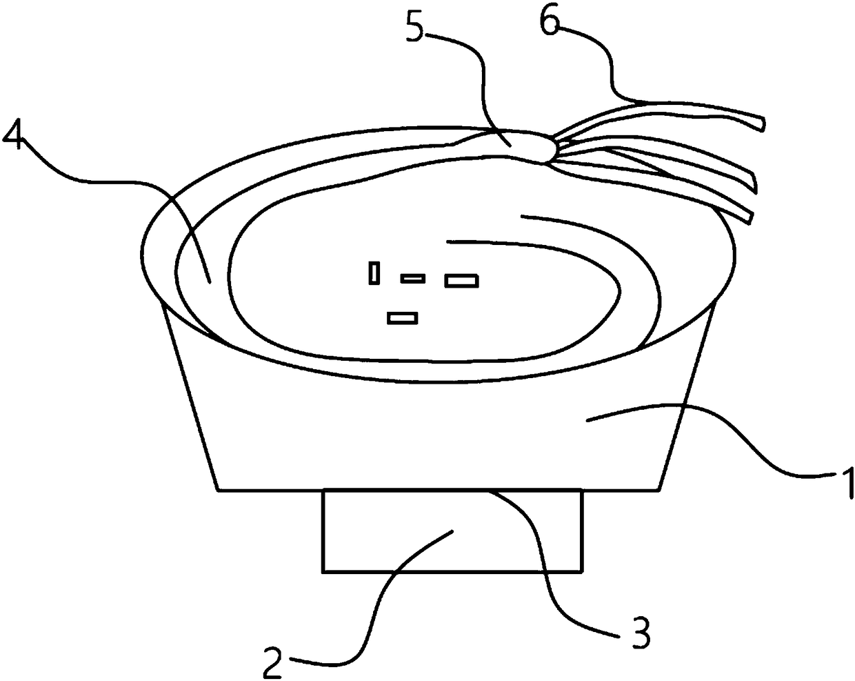
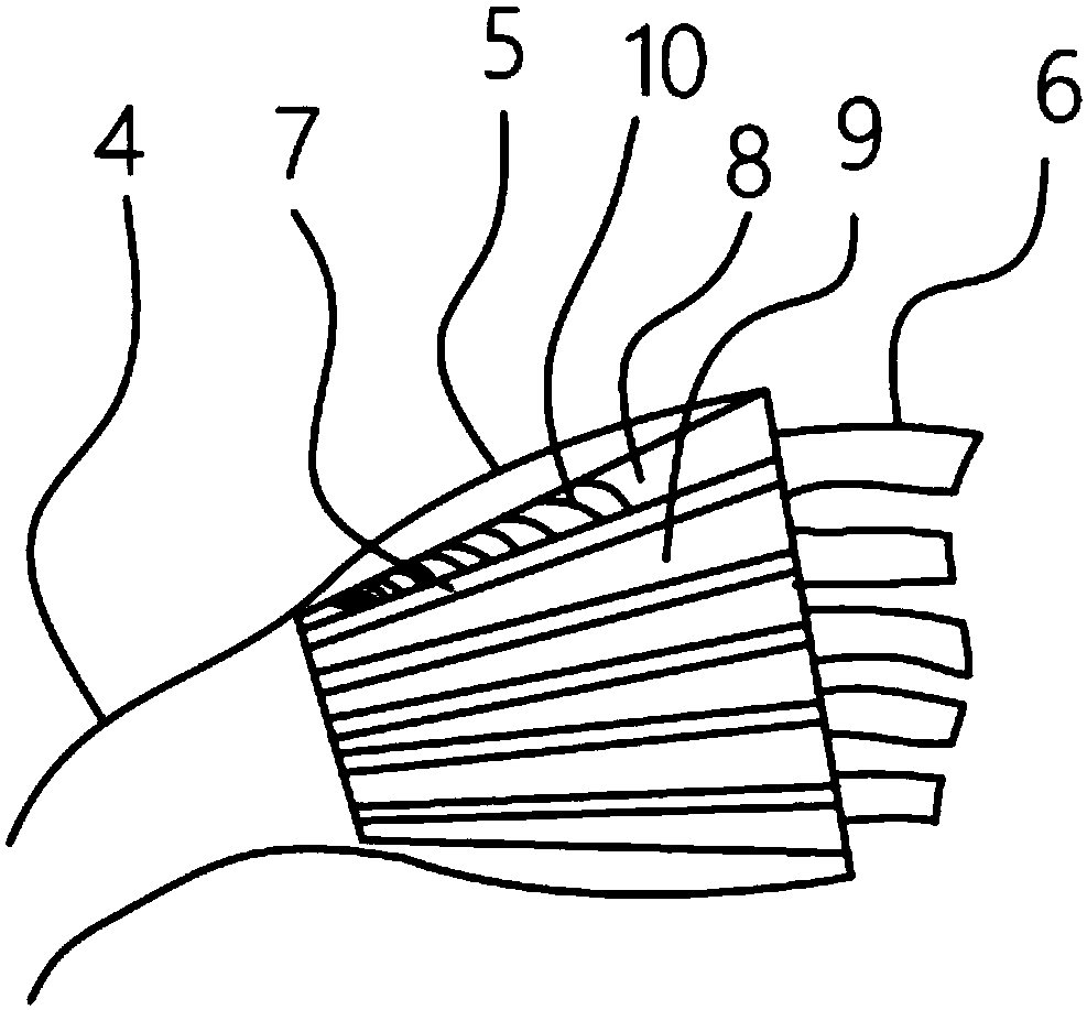
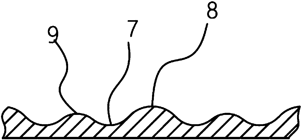
[0022] A metal short tube automatic vibrating feeding tray, such as figure 1 and figure 2 As shown, the feeding tray includes a base 1 with a vibrator 2, and a feeding hopper 3 for loading short metal pipes is arranged above the base 1. The inner wall of the feeding hopper 3 is provided with a spirally rising feeding channel 4, which is characterized in that the feeding channel 4 The upper part is provided with a directional disk 5 for directional arrangement of short metal pipes, and several feeding branch channels 6 are arranged behind the directional disk 5, and several directional channels 7 are arranged on the directional disk 5, and the feeding branch channels 6 One-to-one correspondence with the directional road 7, the bottom of the directional road 7 is an arc surface, and the two sides of the directional road 7 are respectively provided with a high directional surface 8 and a low directional surface 9 with different heights, and the high directional surface 8 and the...


PUM


Abstract

The invention relates to the technical field of mechanical processing, in particular to an automatic vibration feeding tray for metal short tubes. The automatic vibration feeding tray for the metal short tubes comprises a base provided with a vibrator, wherein a feeding hopper for containing the metal short tubes is arranged on the base, and a spiraling feeding channel is formed in the inner wall of the feeding hopper. The automatic vibration feeding tray is characterized in that an orientation tray part for carrying out orientation arrangement on the metal short tubes is arranged at the upper part of the feeding channel; a plurality of feeding branch channels are formed at the rear of the orientation tray part; a plurality of orientation channels are formed in the orientation tray part; arc surfaces are arranged at the bottoms of the orientation channels; high orientation surfaces and low orientation surfaces at different heights are arranged at the two sides of the orientation channels respectively; and the high orientation surfaces and the low orientation surfaces are arc surfaces. With the adoption of the automatic vibration feeding tray, longitudinal distribution of the metal short tubes can be realized, one-to-many rapid supply can be realized, and the production efficiency is improved.

Description

technical field [0001] The invention relates to the technical field of mechanical processing, in particular to an automatic vibrating feeding tray for short metal tubes. Background technique [0002] With the popularization of automation and semi-automation in various industries of the economy, automatic feeding devices have become an indispensable link in the production line. [0003] The automatic feeding vibrating plate is a kind of feeding equipment with automatic orientation and sorting. Its working purpose is to automatically and orderly arrange the disordered workpieces neatly and accurately through vibration to transport them to the next process. The vibrating plate is an auxiliary equipment for automatic assembly machinery, which can discharge various products in an orderly manner. It can cooperate with automatic assembly equipment to assemble various parts of the product into a complete product. [0004] The automatic feeding vibrating plate is mainly composed of...

Claims


Application Information

Patent Timeline
Patent Type & Authority Patents(China)
IPC IPC(8): B65G47/14
CPCB65G47/1492B65G2201/0276
Inventor 黄春平
Owner PINGHU PINYAO MACHINERY AUTOMATION CO LTD
Learn More