Multi-cylinder dressing case inner container conveying mechanism

A technology of conveying mechanism and cosmetic box, which is applied in the direction of conveying objects, transportation and packaging, etc., can solve the problems of low efficiency, unsatisfactory effect, troublesome taking the inner tank, etc., and achieve high efficiency.

Active Publication Date: 2016-11-09
汕头市誉东包装制品有限公司
5 Cites 0 Cited by

AI-Extracted Technical Summary

Problems solved by technology

[0002] Existing cosmetic boxes generally use a fixed liner in the box body, and the liner is generally taken and placed ...

Abstract

The invention discloses a multi-cylinder dressing case inner container conveying mechanism which comprises a rack. A through hole is formed in the middle of the left side of a top plate of the rack, a grabbing through hole is formed in the middle of the right side of the top plate of the rack, and vertical plates are fixed to the left side and the right side of the top plate of the rack. The two ends of each of two guide rods are fixed to the corresponding vertical plates, the two guide rods are located on the front portions and the rear portions of the vertical plates, and guide blocks are fixed to the front portions and the rear portions of the left end and the right end of an upper connecting plate and inserted into the guide rods in a sleeved mode. A transverse moving air cylinder is fixed to the top faces of the left side of the two guide rods, the end of a push rod of the transverse moving air cylinder extends rightwards and is fixed to the corresponding guide block at the right end of the upper connecting plate, and the upper connecting plate is located between the two guide rods. The multi-cylinder dressing case inner container conveying mechanism can automatically grab and convey inner containers and is very convenient to use and high in efficiency.

Application Domain

Conveyor parts

Technology Topic

Architectural engineering

Image

  • Multi-cylinder dressing case inner container conveying mechanism
  • Multi-cylinder dressing case inner container conveying mechanism
  • Multi-cylinder dressing case inner container conveying mechanism

Examples

  • Experimental program(1)

Example Embodiment

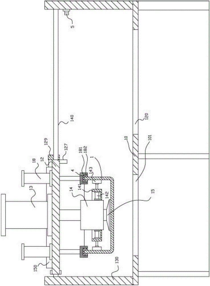
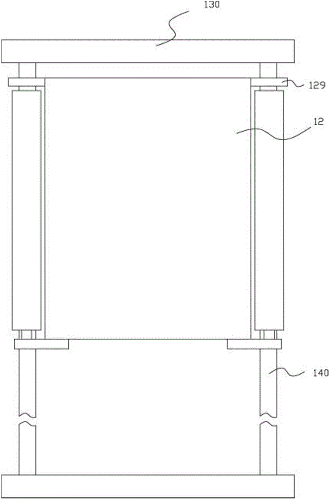
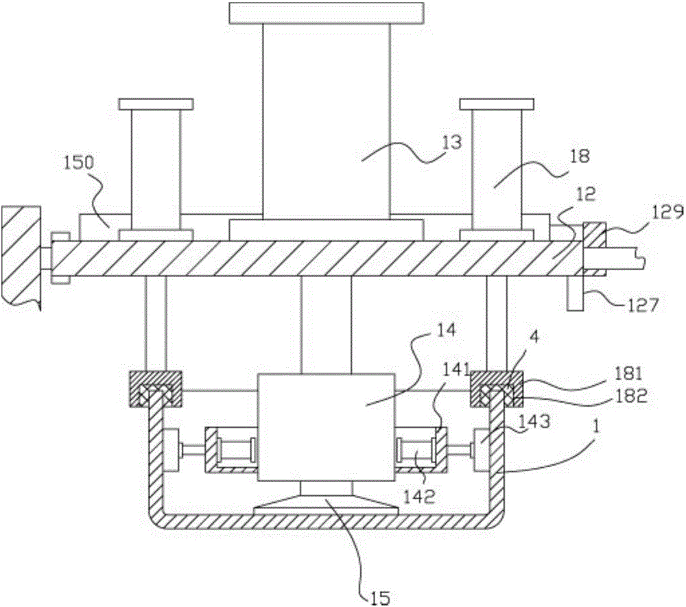
[0014] Example: see Figure 1 to Figure 3 As shown, a multi-cylinder vanity box liner conveying mechanism includes a frame 10, the top plate of the frame 10 has a through hole 101 at the left middle part, and the right middle part of the top plate of the frame 10 has a grasping through hole 120 , The left and right sides of the top plate of the frame 10 are fixed with vertical plates 130, both ends of the two guide rods 140 are fixed on the corresponding vertical plate 130, and the two guide rods 140 are located at the front of the vertical plate 130 and At the rear, the front and rear of the left and right ends of the upper connecting plate 12 are fixed with a guide block 129, the guide block 129 is inserted and sleeved in the guide rod 140, and the top surface at the left side of the two guide rods 140 is fixed The cylinder 150 is moved laterally, and the end of the push rod of the laterally movable cylinder 150 extends to the right and is fixed on the corresponding guide block 129 at the right end of the upper connecting plate 12, which is located between the two guide rods 140;
[0015] The upper part of the top plate of the upper connecting plate 12 has a pushing cylinder 13 in the middle of the top surface. The push rod of the pushing cylinder 13 vertically passes through the top plate of the upper connecting frame 12 and is fixed with a grab block 14, and the bottom surface of the grab block 14 is fixed with a suction cup 15. An annular cover 141 is fixed on the side wall of the grab block 14, and a clamping cylinder 142 is fixed inside the side plate of the ring cover 141. The push rod of the clamping cylinder 142 extends out of the side plate of the ring cover 141 and is hinged with clamping Block 143, the grasping block 14 is inserted into the inner liner 1, the suction cup 15 is adsorbed on the top surface of the bottom plate of the inner liner 1, and the clamping block 143 is pressed against the inner side wall of the inner liner 1.
[0016] Furthermore, a proximity switch 5 is fixed on the vertical plate 130 on the right side of the top plate of the rack 10, and the sensing end of the proximity switch 5 faces the sensing block 127 fixed at the bottom of the right end of the upper connecting plate 12.
[0017] Furthermore, a plurality of side auxiliary cylinders 18 are fixed on the top surface edge of the top plate of the upper connecting plate 12, and the push rods of the side auxiliary cylinders 18 vertically pass through the top plate of the upper connecting plate 12 and are fixed with The pushing block 181 has a groove 182 on the bottom surface of the pushing block 181. The top of the inner liner 1 and the pushing block 181 are inserted into the groove 182; the inner side wall of the groove 182 is fixed with a protective elastic layer 4 to protect The elastic layer 4 is pressed against the side wall of the top of the inner liner 1.
[0018] Working principle: By moving the push rod of the cylinder 150 laterally, the upper connecting plate 12 is moved to the upper part of the grasping through hole 120, and the limit is realized by the proximity switch 5. Then, the push rod of the cylinder 13 is pushed to make the suction cup 15 Move downward and extend the grasping through hole 120 to absorb the inner liner 1 placed under the grasping through hole 120, and then push by the push rod of the clamping cylinder 142, so that the clamping block 143 is pressed against the inner side of the liner 1 The wall is fixed, and then the push rod of the cylinder 13 is pushed to retract, and then the push rod of the cylinder 150 is moved transversely to retract, so that the upper connecting plate 12 moves to the top of the through hole 101 to achieve subsequent installation, which is convenient and efficient in transportation High, good effect.

PUM

no PUM

Description & Claims & Application Information

We can also present the details of the Description, Claims and Application information to help users get a comprehensive understanding of the technical details of the patent, such as background art, summary of invention, brief description of drawings, description of embodiments, and other original content. On the other hand, users can also determine the specific scope of protection of the technology through the list of claims; as well as understand the changes in the life cycle of the technology with the presentation of the patent timeline. Login to view more.

Similar technology patents

Systems and methods for notifying multiple hosts from an industrial controller

ActiveUS8150959B1reusable block of code very difficultimprove efficiency
Owner:ROCKWELL AUTOMATION TECH

Hybrid OLED having improved efficiency

InactiveUS20080284317A1improve efficiency
Owner:GLOBAL OLED TECH

MIMO-OFDM transmitter

InactiveUS20070253504A1improve efficiencyreduce time
Owner:FUJITSU LTD

Classification and recommendation of technical efficacy words

  • Improve efficiency
Why Eureka
Try Eureka