A method for producing methane-rich gas, liquefied petroleum gas and gasoline from synthesis gas

A technology for liquefied petroleum gas and synthesis gas, applied in the field of coal chemical industry, can solve the problems of reduced efficiency and increased energy consumption, and achieve the effect of reducing process energy consumption

Active Publication Date: 2018-01-16
SHANXI FEISHI TECH
View PDF17 Cites 0 Cited by
  • Summary
  • Abstract
  • Description
  • Claims
  • Application Information

AI Technical Summary

Problems solved by technology

[0008] In summary, in the process of coal conversion to produce natural gas, gasoline and liquefied petroleum gas in the existing technology, there are generally problems of large-scale material circulation, increased energy consumption, and reduced efficiency
So far, there is no low-energy integrated technology that can realize the simultaneous production of the above three products

Method used


Image

  • A method for producing methane-rich gas, liquefied petroleum gas and gasoline from synthesis gas
  • A method for producing methane-rich gas, liquefied petroleum gas and gasoline from synthesis gas
  • A method for producing methane-rich gas, liquefied petroleum gas and gasoline from synthesis gas

Examples


Embodiment 1

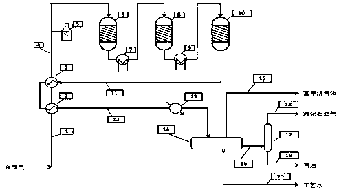
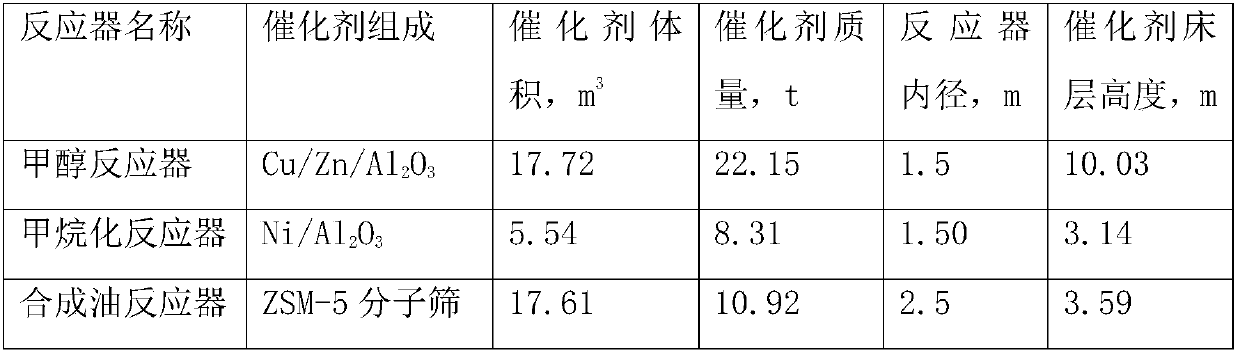
[0060] According to the process shown in the attached figure, the device for producing methane-enriched gas, liquefied petroleum gas and gasoline from syngas was established. The main equipment involved and the catalyst loading conditions are shown in Table 1.

[0061] Table 1. Example 1 reactor and catalyst loading data

[0062]

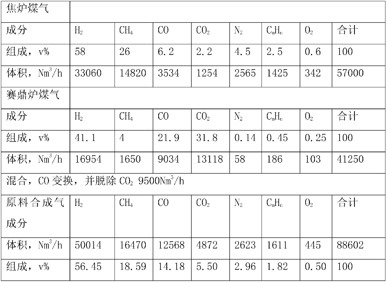
[0063] Embodiment 1 uses coke oven gas and Saiding furnace gas as raw materials. Among them, the coke oven gas is a coke oven gas delivered from a set of 2 million tons / year coking equipment, and the gasifier is a Saiding furnace with a diameter of 3.8m and a coal input of 16.8t / h. After the above two gases are mixed, after purification, CO conversion, CO 2 After removal and other processes, it is used as the raw material gas of this embodiment. The composition and flow rate of relevant gases are shown in Table 2.

[0064] Table 2. The feed gas source and composition of embodiment 1

[0065]

[0066] Raw material gas H of embodiment 1 2 / ...

Embodiment 2

[0087] According to the process shown in the attached figure, the device for producing methane-enriched gas, liquefied petroleum gas and gasoline from syngas is established, and the main equipment and catalyst loading conditions involved are shown in Table 7.

[0088] Table 7. Example 2 Reactor and Catalyst Packing Data

[0089]

[0090] Embodiment 2 uses Saiding furnace gas as raw material. The diameter of the Saiding furnace is 5.0m, the gasification pressure is 5.6MPa, the coal input of a single Saiding furnace is 1500t / d Saiding furnace, and the number of online Saiding furnaces is 10. After the Saiding furnace gasification gas is purified, CO is converted and CO is removed 2 and other operations, the operating volume, gas flow rate and composition of relevant sections are shown in Table 8.

[0091] Table 8. Feed gas source and composition of embodiment 2

[0092]

[0093]

[0094] After purification, conversion and decarburization sections, the pressure of the...


PUM


Abstract

A method for producing methane-enriched gas, liquefied petroleum gas and gasoline from synthesis gas. After being heated, the raw material synthesis gas enters a methanol reactor equipped with a methanol synthesis catalyst to react to generate methanol; the outlet material of the methanol reactor enters a methanol reactor equipped with a Catalyst reacts in the methanation reactor to generate methane; the outlet material of the methanation reactor enters the synthetic oil reactor equipped with synthetic oil catalyst to be converted into liquefied petroleum gas and gasoline; the outlet material of the synthetic oil reactor enters the oil-water-gas three-phase separator , the gas phase product obtained by separation is methane-rich gas, and the water phase product is sent to the outside for treatment; the oil phase product enters the rectification tower for rectification separation, and the liquefied petroleum gas product is obtained at the top of the tower, and the gasoline product is obtained at the bottom of the tower. The invention has the advantages of low energy consumption and high efficiency.

Description

technical field [0001] The invention belongs to a method for preparing methane-rich gas, liquefied petroleum gas and gasoline from synthesis gas, and belongs to the technical field of coal chemical industry. Background technique [0002] China's primary energy endowment is characterized by rich coal but little oil and lack of gas, that is, coal resources are abundant, oil resources are short, and natural gas resources are few. With the development of my country's national economy and the increasing awareness of environmental protection, my country's demand for clean energy is growing at an unprecedented rate. Although coal will still occupy a dominant position in the composition of my country's primary energy for a long time to come, its consumption pattern must and has undergone significant changes, which has led to coal-to-natural gas, coal-to-liquefied petroleum gas, gasoline, and diesel oil. and other modern coal chemical technology development. [0003] There are a lar...

Claims


Application Information

Patent Timeline
Patent Type & Authority Patents(China)
IPC IPC(8): C10G3/00C10L3/08C10L3/12
CPCY02P30/20
Inventor 李文怀李凯旋杨晋杨恒李世扬
Owner SHANXI FEISHI TECH
Why Eureka
Try Eureka