Positioning device for connection plate of steel column and steel beam

A technology of positioning device and connecting plate, applied in the direction of building and building structure, can solve the problems of low efficiency, prone to error, connecting and fixing of connecting plate, etc. Effect

Inactive Publication Date: 2016-11-09
XUZHOU ZM BESTA HEAVY STEEL STRUCTURE
View PDF7 Cites 8 Cited by
  • Summary
  • Abstract
  • Description
  • Claims
  • Application Information

AI Technical Summary

Problems solved by technology

[0002] As we all know: in the structural dimensions of steel columns and steel beams, the main components of steel structure buildings, the angle of the connecting plate is the key item of key control, because: if there is an angle error in the connecting plate, the steel columns or steel beams cannot be connected through the connection. The connection and fixation of the board, although it can be connected and fixed by force, will appear linear bending in the horizontal and vertical directions. Many, every time a variety is produced, it must be re-staked and marked, so the efficiency is relatively low. In addition, the marking and setting is affected by the technical level of personnel and environmental factors, and errors or even serious errors are prone to occur. The positioning device for the steel column and steel beam connection plate of steel structure buildings that relies on manual lofting and marking is particularly necessary

Method used


Image

  • Positioning device for connection plate of steel column and steel beam
  • Positioning device for connection plate of steel column and steel beam
  • Positioning device for connection plate of steel column and steel beam

Examples


Embodiment Construction

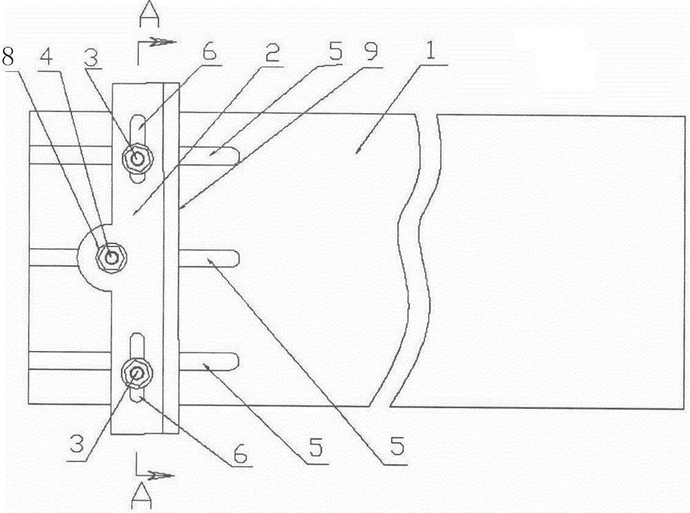
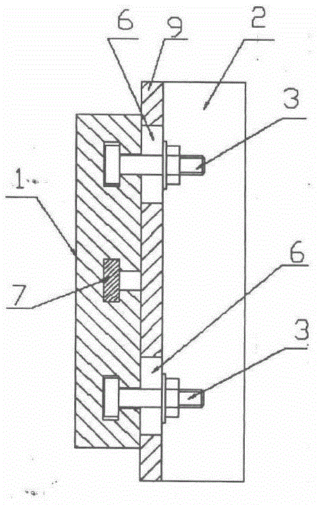
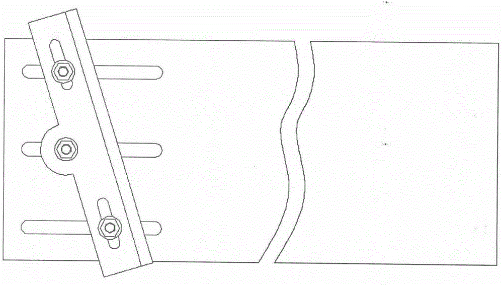
[0011] The positioning device for the connection plate between a steel column and a steel beam includes a base (1), an angle adjustment plate (2), a T-shaped bolt (3), a rotating shaft (4), a T-shaped slot (5), and a strip Holes (6), sliders (7), nuts (8), and baffles (9), three T-shaped slots (5) with equal intervals and parallel to each other are formed at one end of the base (1), and in the middle A slide block (7) is arranged in the T-shaped groove (5) of the slide block (7), and a rotating shaft (4) is vertically fixed above the sliding block (7), and an angle adjustment plate (2) is installed on the rotating shaft (4). The top of rotating shaft (4) is shaped on screw thread, and a nut (8) is installed on this threaded position, and this nut (8) guarantees that angle adjustment plate can rotate on rotating shaft (4) but can not come off, and at described angle Both ends of the adjustment plate (2) are symmetrically shaped with long holes (6), and a T-head bolt (3) is arra...


PUM


Abstract

The invention discloses a positioning device for a connection plate of a steel column and a steel beam and belongs to the technical field of steel structure buildings. Three T-shaped grooves are formed in one end of a base at equal intervals and in parallel. A sliding block is arranged in the middle T-shaped groove. A rotary shaft is vertically fixed to the sliding block. An angle adjusting plate is installed on the rotary shaft. Long strip-shaped holes are symmetrically formed in the two ends of the angle adjusting plate. A T-shaped end bolt is arranged in each long strip-shaped hole. A baffle is fixed along an inner edge opening of the angle adjusting plate, and the baffle and the angle adjusting plate are perpendicular to each other. The positioning device has the advantages that universality is good, the labor efficiency during production is high, and the product quality is easily ensured.

Description

technical field [0001] The invention relates to a steel structure building, in particular to a positioning device for a steel column and a steel beam connecting plate in a steel structure building, and belongs to the technical field of steel structure building. Background technique [0002] As we all know: in the structural dimensions of steel columns and steel beams, the main components of steel structure buildings, the angle of the connecting plate is the key item of key control, because: if there is an angle error in the connecting plate, the steel columns or steel beams cannot be connected through the connection. The connection and fixation of the board, although it can be connected and fixed by force, will appear linear bending in the horizontal and vertical directions. Many, every time a variety is produced, it must be re-staked and marked, so the efficiency is relatively low. In addition, the marking and setting is affected by the technical level of personnel and envi...

Claims


Application Information

Patent Timeline
Patent Type & Authority Applications(China)
IPC IPC(8): E04B1/24E04B1/58
CPCE04B1/2403E04B1/58E04B2001/2415E04B2001/2439E04B2001/5862
Inventor 王善文王智达卓震李响
Owner XUZHOU ZM BESTA HEAVY STEEL STRUCTURE
Why Eureka
Try Eureka