Impact compound thread connection rock drilling tools

A threaded connection and impact technology, which is applied in the direction of drilling equipment, earthwork drilling, drill pipe, etc., can solve the problems of increased impact force, local stress concentration, reduced load-bearing force arm, and external thread fracture, etc., to achieve anti-axial Strong axial load capacity, good bending moment resistance, and good root strength

Active Publication Date: 2018-08-17
GUIYANG JIESHENG TECH IND DEV
View PDF7 Cites 0 Cited by
  • Summary
  • Abstract
  • Description
  • Claims
  • Application Information

AI Technical Summary

Problems solved by technology

In actual use, even if the fit relationship between the two inner tapered surfaces and the shaft shoulder is handled well (the interference degree of over-positioning is small), but when the drilling tool is deformed under load (especially near the end surface of the inner thread) It is very likely that the bending moment will be borne by the right-angled end face of the drill rod shaft shoulder (or the corresponding internal thread end face) and the cone surface at the front end of the external thread section of the drill rod, resulting in a sudden reduction in the bearing force arm and an increase in the local stress of the bending moment
At the same time, when the right-angled end face of the shaft shoulder (or the end face of the internal thread) is not uniformly stressed, the impact force transmitted (the main load transmitted by the combined component) will further increase the degree of local stress concentration, resulting in failure of the part in a short time
[0006] In addition, "CN10289110B" discloses a "drill bit for percussive rock drilling". This patent uses a section of internal thread to replace the relief groove in the threaded blind hole, although it can overcome the thinner trouser wall at the relief groove. defects, but the internal thread processing is more difficult
Not only that, due to the cancellation of the undercut, the internal thread extends all the way to the bottom of the threaded blind hole; therefore, a stress concentration will be formed between the end of the internal thread and the bottom of the threaded blind hole, resulting in the intersection of the internal thread and the bottom of the hole prone to cracks
In addition, since the drill rod of this patent is not equipped with a shaft shoulder, the end face of the trouser body and the thread occlusal line are similar to a simply supported beam structure, and the external thread will inevitably break at the thread occlusal line under the action of the bending moment, which is also the current traditional external thread. The main failure mode of thread

Method used


Image

  • Impact compound thread connection rock drilling tools
  • Impact compound thread connection rock drilling tools
  • Impact compound thread connection rock drilling tools

Examples


Embodiment 1

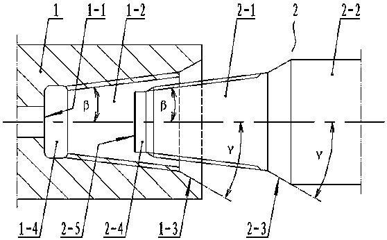
[0028] Such as Figure 1~3 As shown: the trouser body 1 of the drill bit is provided with a tapered threaded blind hole 1-2, and the drill rod 2 is connected with the threaded blind hole through the external threaded section 2-1 located at its front part; the taper bottom of the threaded blind hole The angle β between the generatrix of the hole and the axis of the bottom hole is 1-10°, preferably 5°.

[0029] The front end of the external thread section 2-1 has a cylindrical transition section 2-4 with a diameter smaller than the minimum cross-sectional diameter of the threaded blind hole 1-2, and the length of the transition section is less than or equal to the thread end of the threaded blind hole 1-2 and the bottom of the hole A distance of 1-1; when the external threaded section 2-1 is tightened with the threaded blind hole 1-2, the front end face 2-5 of the transition section 2-4 is in contact with the bottom 1-1 of the threaded blind hole 1-2.

[0030] In order to impro...

Embodiment 2

[0032] On the basis of the foregoing embodiments, the present invention can also adopt the following structures: in order to improve the strength of the drill rod 2, the drill rod 2 adopts a stepped shaft structure with a middle section 2-2; in order to avoid stress concentration, the external thread section 2- 1 and the middle section 2-2 are connected and transitioned through the conical shoulder 2-3; the angle γ between the shoulder 2-3 and the axis of the drill rod 2 is 1-10°, preferably 4°. In order to improve the bending strength at the end of the external thread of the drill rod 2, the orifice of the threaded blind hole 1-2 has an inner tapered surface 1-3 matching the shaft shoulder 2-3. When the external threaded section 2-1 is tightened with the threaded blind hole 1-2, only the front end face 2-5 of the transition section 2-4 is in contact with the bottom 1-1 of the threaded blind hole 1-2, while the shoulder 2- The outer tapered surface of 3 is not in contact with ...

Embodiment 3

[0034] On the basis of the above embodiments, the present invention can also adopt the following structure: in order to facilitate the processing of internal threads, an undercut 1-4 is provided between the threaded blind hole 1-2 and the hole bottom 1-1.


PUM


Abstract

The invention discloses an impact-type composite threaded-connection drilling tool which belongs to an impact-type drilling drill. The invention aims to provide the impact-type drilling tool of which a trouser body and a drilling rod have long service lives. The tool comprises the trouser body and the drilling rod which is in a fitting connection with a taper blind hole via outer threads, wherein when an outer thread section (2-1) and a threaded blind hole (1-2) are screwed down, the front end face (2-5) of a transition section (2-4) can touch the hole bottom (1-1) of the threaded blind hole (1-2); and a thread tooth shape of the threaded blind hole (1-2) is composed of a straight-line inner thread tooth top (3), a curve-shaped inner thread tooth bottom (5) and two sections of straight-line inner thread tooth sides (4), and a thread tooth shape of the outer thread section (2-1) is composed of a straight-line outer thread tooth bottom (6), a curve-shaped outer thread tooth top (8) and two sections of straight-line outer thread tooth sides (7). The drilling tool disclosed by the invention is characterized in that the trouser body and the drilling rod are not broken easily; processing is easy; and the service lives are long. The drilling tool is an improved structure of the impact-type drilling tool.

Description

technical field [0001] The invention relates to an impact type rock drilling tool, in particular to an impact type composite thread connection rock drilling tool. Background technique [0002] At present, the percussive rock drilling tool is usually formed by connecting the drill rod with the trouser body of the drill bit through threads. During the rock drilling process, the stress on the drill rod and the trouser body is relatively complicated and harsh, which may easily cause the drill tool to fail and affect the life of the drill tool. Observation found that there are two main forms of drilling tool failure: 1) fracture occurs near the end of the external thread section of the drill rod; 2) the area between the end of the internal thread of the blind threaded hole of the trouser body and the bottom of the screw hole is prone to fracture. After analysis, the main reasons for the fracture of the drill rod or trousers are as follows: [0003] 1) Since the stress is mostly...

Claims


Application Information

Patent Timeline
Patent Type & Authority Patents(China)
IPC IPC(8): E21B17/042
CPCE21B17/0426
Inventor 黄献萩武一苇
Owner GUIYANG JIESHENG TECH IND DEV
Why Eureka
Try Eureka