
Suspension device of sucker rod

A suspension device and sucker rod technology, applied in drill pipe, drilling equipment, earthwork drilling, etc., can solve problems such as reducing oil production efficiency, and achieve the effect of reducing workover costs

Inactive Publication Date: 2016-11-09
CHINA PETROLEUM & CHEM CORP
View PDF4 Cites 1 Cited by
  • Summary
  • Abstract
  • Description
  • Claims
  • Application Information

AI Technical Summary

Problems solved by technology

[0004] Therefore, it is necessary to design a sucker rod suspension device to complete the gas injection process without lifting the rod string, so as to reduce the increased workover costs caused by lifting and lowering the sucker rod and avoid reducing oil production efficiency

Method used


Image

  • Suspension device of sucker rod
  • Suspension device of sucker rod

Examples


Embodiment Construction

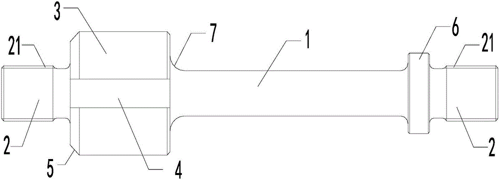
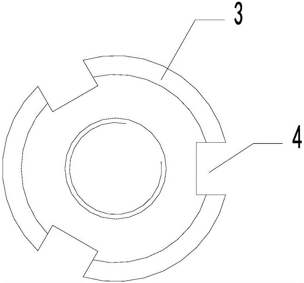
[0017] In order to better understand the purpose, structure and function of the present invention, the sucker rod suspension device of the present invention will be further described in detail below in conjunction with the accompanying drawings.

[0018] Such as Figure 1-2 As shown, the sucker rod suspension device of the present invention includes a cylindrical suspension body 3, the two sides of the suspension body 3 are connected with connecting parts 2, the surface of the connecting part 2 has external threads 21, and the connecting part 2 is used for connecting the pumping rod. The oil rod, the suspension body 3 is provided with at least one groove 4 penetrating the suspension body 3 in the axial direction. Before the gas injection construction, pull out the sucker rod, connect the sucker rod suspension device with the sucker rod in the well, and seat the sucker rod suspension device in the tubing hanger to realize the sucker rod suspension. Thus, when the suspension bo...


PUM


Abstract

The invention discloses a suspension device of a sucker rod. The suspension device of the sucker rod comprises a cylindrical suspension body. Connection parts are connected to the two sides of the suspension body, and the surface of each connection part is provided with an outer thread. The connection parts are used for being connected with the sucker rod. The suspension body is provided with at least one groove which penetrates through the suspension body in the axial direction. When the suspension body is placed in an oil tube suspension unit, the grooves can form a channel for air injection. By means of the suspension device of the sucker rod, the air injection process can be completed without lifting a rod string, so that the increased well repairing cost caused by ascending and descending the sucker rod is reduced, and the oil production efficiency is prevented from being reduced.

Description

technical field [0001] The invention relates to a downhole tool for an oil field, in particular to a suspension device for a sucker rod. Background technique [0002] With the continuous deepening of gas injection and three recovery work, gas injection is required to supplement the formation energy after the energy of the mechanically pumped well is attenuated; at present, the gas injection of the rod pump or the pumping string of the thickening pump needs to be carried out after the sucker rod is pulled out. In the gas injection process, the workover rig and its auxiliary equipment are required to lift the sucker rod, and the workover period is about 3 days; after the gas injection is completed, the pumping is required, and the sucker rod must be lowered again during production, increasing the workover period by about 3 days; thereby greatly affecting the production efficiency, but also increased the cost of workover twice. [0003] In addition, due to the low pressure of ...

Claims


Application Information

Patent Timeline
IPC IPC(8): E21B19/02
CPCE21B19/02
Inventor 任文博任爱军程洪李勇宋正聪蒋林刘刚波刘毅赵想安董茂泰张大志田磊祁世文赵跃杨小辉徐鑫许开春于国龙谷旭郭文肖谢菲杨烽芦海涛刘利清王幼黄米娜李桂云王虹付栋吴慧马国建陈明仁李青姚蓓刘洪源
Owner CHINA PETROLEUM & CHEM CORP
Learn More