Oil pumping pipe rod storage, cleaning and maintenance system for drilling/workover treatment

A maintenance system and oil pumping pipe technology, which is applied to drill pipes, drill pipes, drilling equipment, etc., can solve the problems of inability to fully collect and discharge waste oil and wastewater, not meeting the requirements of green well site construction, and low efficiency of well site cleaning. To save manpower, improve work efficiency, small footprint

Pending Publication Date: 2021-02-12
西安宝德智能科技有限公司
View PDF0 Cites 1 Cited by
  • Summary
  • Abstract
  • Description
  • Claims
  • Application Information

AI Technical Summary

Problems solved by technology

[0004] 1. Manual placement of oil pipes takes up a large area, high labor intensity and low efficiency
[0005] 2. The contaminated soil during the placement and transportation of oil pipes cannot be cleaned up, which does not meet the requirements for green well site construction
[0006] 3. There is no enclosure during the cleaning process of the oil pipe, and the waste liquid is splashed everywhere
[0007] 4. The on-site cleaning efficiency of the well site is low, and it is necessary to queue up to wait for the cleaning vehicle
[0008] 5. Waste oil and wastewater in workover operations cannot be fully collected and discharged
[0009] 6. The number and length statistics of pipe rods and pipe replacement automation are low, and the flaw detection is manual flaw detection
[0010] 7. The existing operation method requires a lot of human resources, and involves multi-industry work cooperation, and the average labor cost is the highest in the oil extraction industry

Method used


Image

  • Oil pumping pipe rod storage, cleaning and maintenance system for drilling/workover treatment
  • Oil pumping pipe rod storage, cleaning and maintenance system for drilling/workover treatment
  • Oil pumping pipe rod storage, cleaning and maintenance system for drilling/workover treatment

Examples


Embodiment Construction

[0061] The detailed description and technical content of the present invention are described below with the accompanying drawings, but the accompanying drawings are only provided for reference and description, and are not intended to limit the present invention.

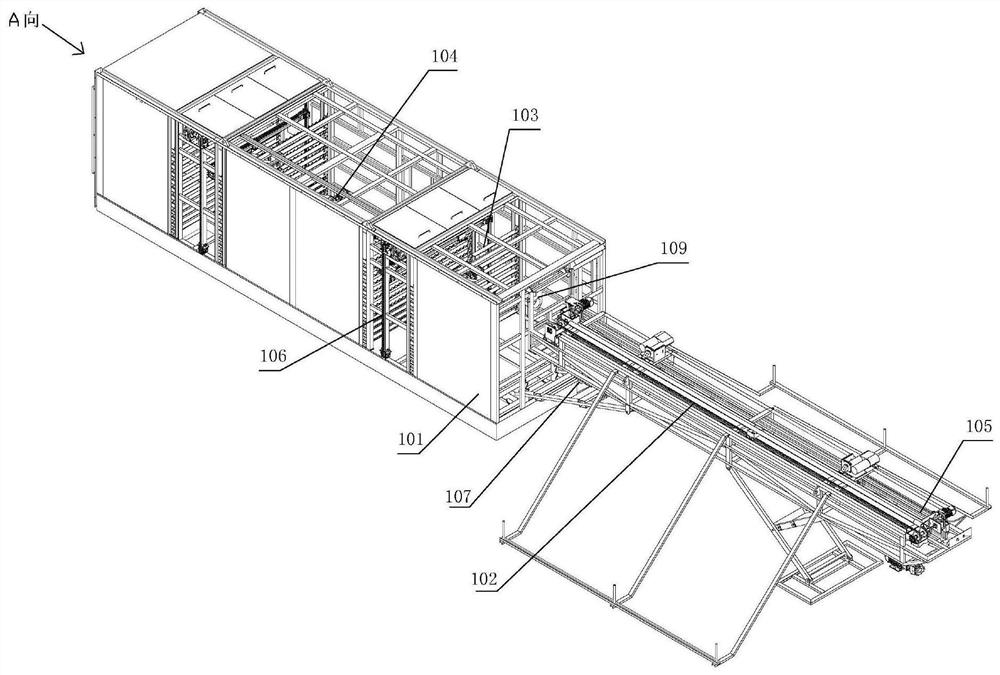
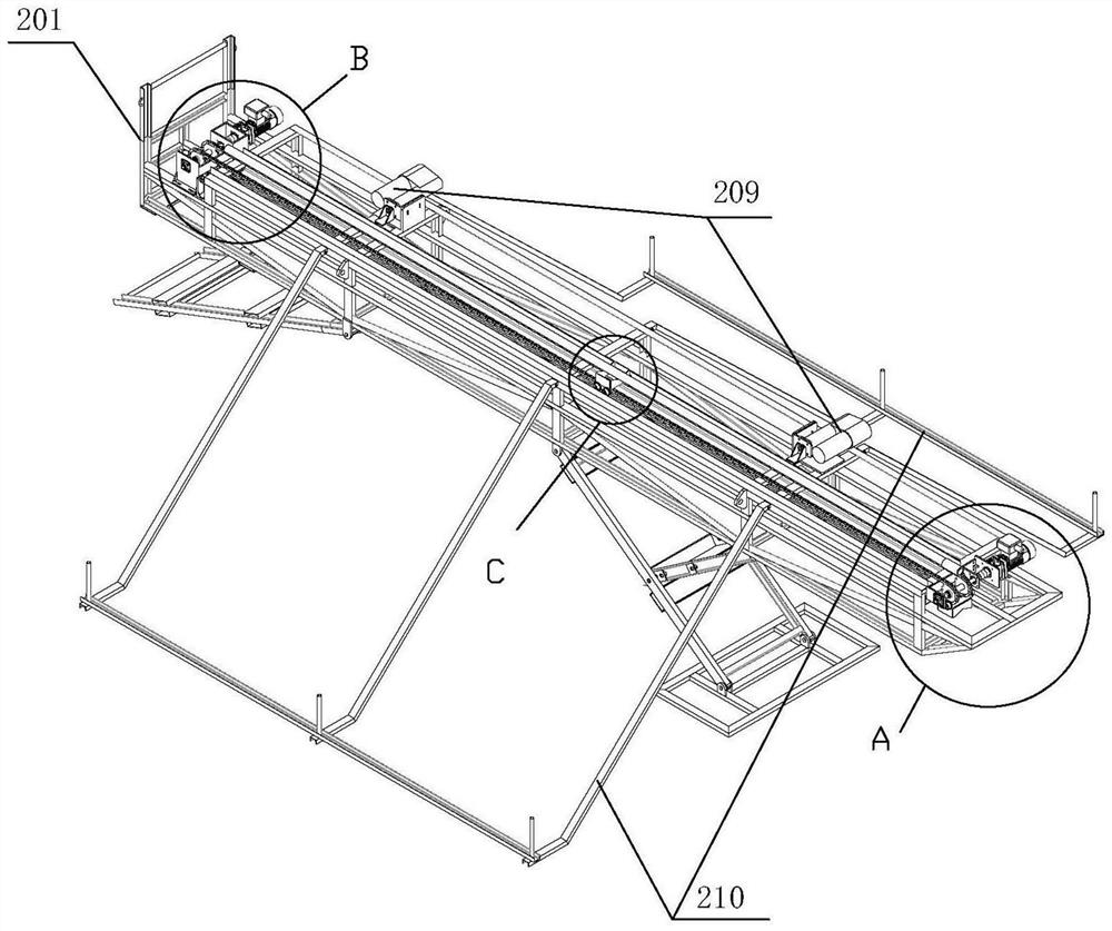
[0062] Below we combine figure 1 , 2 , the general scheme of the present invention is specified:

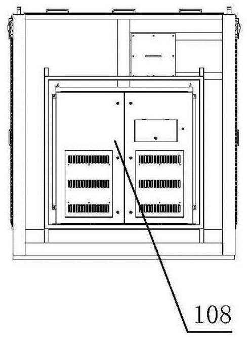
[0063] see figure 1 , 2 , the present invention includes a main pipe box 101, a pipe rod conveying system 102, a layered bracket structure 103, a pipe rod receiving system 104, an automatic cleaning system 105, a pipe rod placement system 106, an automatic sewage discharge system 107, a control system 108, a flaw detection system System 109 and pipe rod length measurement system.

[0064] The main pipe box 101 is welded by section steel, the top is laid with steel grid, the front end is open, the remaining surface is covered with steel plate, the base is divided into several cavities, each part of the bottom cavity ...


PUM


Abstract

The invention relates to an oil pumping pipe rod storage, cleaning and maintenance system for drilling/workover treatment. The system comprises a main pipe box, a pipe rod conveying system, a layeredbracket structure, a pipe rod bearing system, an automatic cleaning system and a pipe rod placing system. The rear end of the pipe rod conveying system is hung at the front end of the main pipe box, the pipe rod bearing system is arranged in the main pipe box and corresponds to the pipe rod conveying system in position, the pipe rod placing system and the layered bracket structure are both arranged in the main pipe box, and the automatic cleaning system is arranged outside the main pipe box and corresponds to the layered bracket structure in position. The operation efficiency can be improved,the well repairing cost is reduced, and the natural environment is protected.

Description

technical field [0001] The invention relates to a mechanized well workover operation device in the petroleum industry, in particular to a storage, cleaning and maintenance system for sucker pipes and rods in drilling / workover operations. Background technique [0002] The workover of pumping wells is an essential operational measure in the development and production of oilfields. At present, most oil fields use traditional equipment to operate, and two workers are required to be responsible for the transportation and discharge of the sucker pipe rod. The working environment is harsh, the labor intensity of the workers is high, and there are safety hazards in the operation process. Secondly, oil pipes are polluted by crude oil dripping during transportation and storage. The way to prevent pollution in the traditional process is to spread the three-proof cloth on the ground of the entire workover operation to collect oil pollution. Due to the high cost of the three-proof cloth,...

Claims


Application Information

Patent Timeline
Patent Type & Authority Applications(China)
IPC IPC(8): E21B19/14E21B19/15B08B9/043B08B13/00
CPCB08B9/043B08B13/00E21B19/14E21B19/155
Inventor 赵敏苏国龙刘宇航吴永宽李立春周滕凯王乐
Owner 西安宝德智能科技有限公司
Why Eureka
Try Eureka