

Oil tube centralizer
A technology of centralizer and oil pipe, applied in drilling pipe, casing, drilling equipment and other directions, can solve the problems of increasing workover costs of oil and water wells, workload of large workover operations, and difficulty in removing jams, etc., and achieves significant economic benefits, The effect of reducing the cost of well workover and the difficulty of unblocking work
- Summary
- Abstract
- Description
- Claims
- Application Information
AI Technical Summary
Problems solved by technology
Method used
Image

Examples
Embodiment Construction
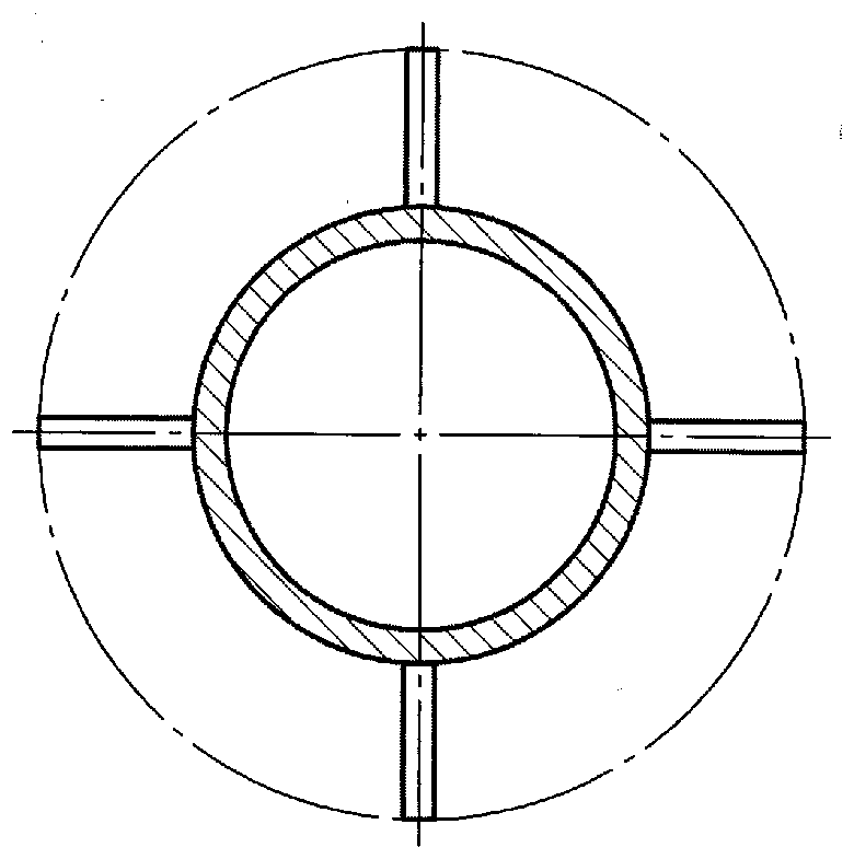
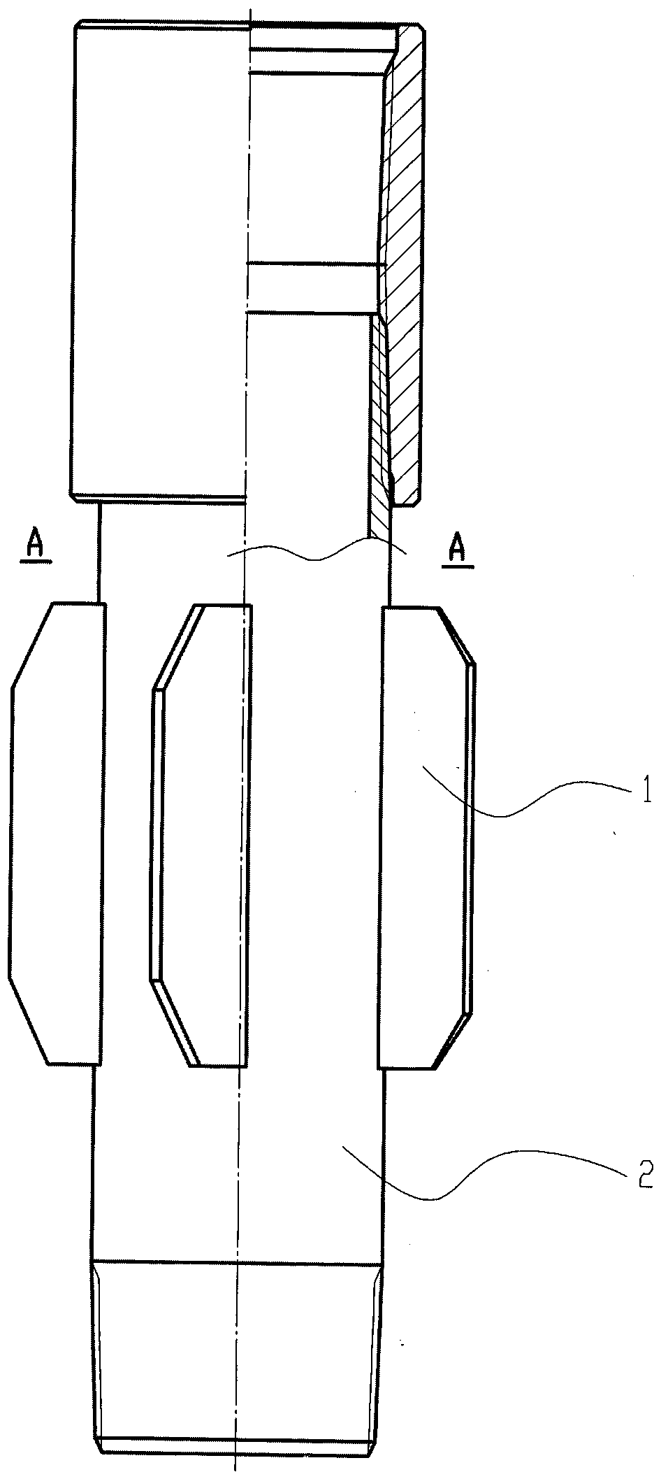
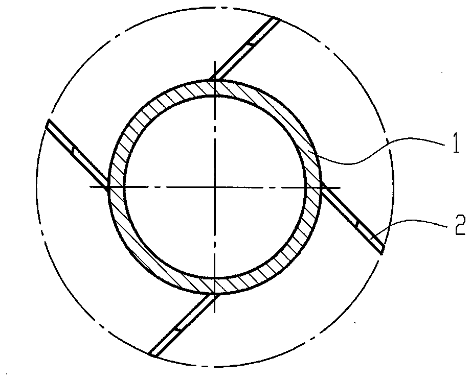
[0009] Attached below figure 2 , 3 Embodiments of the present invention are further described:
[0010] Depend on figure 2 , 3 It can be seen that the embodiment of the present invention includes a centralizing sheet 1 and an inner pipe 2, and the centralizing sheet 1 is installed on the inner pipe 2 (welded), the quantity of the centralizing sheet 1 is 3-8 pieces, and the two ends of the centralizing sheet 1 have chamfers, The axis of the centralizing sheet 1 and the inner tube 2 is at an angle of 20-70︒ (cannot form a plane), and the outer edges of several centralizing sheets 1 are on the same cylinder (points on the outer edges of several centralizing sheets 1 can be connected form a circle), the axis of the cylinder is coaxial with the axis of the inner tube 2.
[0011] The quantity of righting piece 1 is generally 4, and the included angle of the axis of righting piece 1 and inner pipe 2 is generally 45︒. The thickness of the centralizing sheet 1 is generally 3-8 m...
PUM
 Abstract
Description
Claims
Application Information