An optical fiber longitudinal stripping device

A longitudinal and optical fiber technology, which is applied in the field of optical fiber longitudinal stripping devices, can solve the problems of inability to accurately control the cutting depth of the cutter head, uneven force on the optical cable and sliding left and right, affecting the cutting of the cutter head, etc. Uniform force and cost-saving effect

Active Publication Date: 2019-06-21
STATE GRID SHANDONG ELECTRIC POWER +1
View PDF5 Cites 0 Cited by
  • Summary
  • Abstract
  • Description
  • Claims
  • Application Information

AI Technical Summary

Problems solved by technology

When the existing optical cable stripping device fixes the optical cable, grooves or a single pulley are often used to fix the optical cable, which causes the optical cable to slide left and right during the stripping process, which affects the cutting of the cutter head and easily damages the fiber core; the existing The optical cable stripping device cannot accurately control the cutting depth of the cutter head, and it is easy to cut to the fiber core

Method used


Image

  • An optical fiber longitudinal stripping device
  • An optical fiber longitudinal stripping device
  • An optical fiber longitudinal stripping device

Examples


Embodiment Construction

[0010] In order to clearly illustrate the technical features of this solution, the present invention will be described in detail below through specific implementation modes and in conjunction with the accompanying drawings.

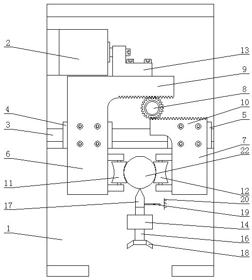
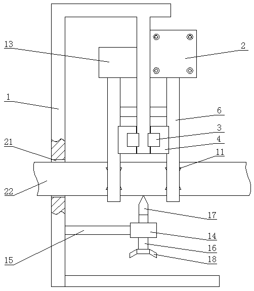
[0011] Such as Figure 1 ~ Figure 2 As shown, the present invention comprises frame 1, and the top of frame 1 is provided with cylinder 2, and the frame 1 below cylinder 2 is provided with two sets of clamping devices, and two sets of clamping devices are arranged symmetrically. Each set of clamping device includes a slide rail 3 arranged horizontally, the first slide block 4 and the second slide block 5 are provided on both sides of the slide rail 3, and the first slide block 4 is provided with a first movable plate 6 , the second slider 5 is provided with a second movable plate 7, the frame 1 between the first movable plate 6 and the second movable plate 7 is provided with a gear 8 which is movably connected with it, and the first movable plate 6 is pro...


PUM


Abstract

The invention relates to an optical fiber longitudinal stripping device. The device comprises a frame. An upper portion of the frame is provided with an air cylinder. The frame below the air cylinder is provided with two sets of clamping devices. The two sets of clamping devices are arranged symmetrically. A piston rod of the air cylinder is connected to a first movable plate of two sets of clamping devices through a first connection board. A lower portion of the frame is connected to a knife holder through a second connection board. The knife holder is located at a position which is between a first pulley and a second pulley and is below the first pulley and the second pulley. A screw passes through the knife holder and is connected with a screw thread. An upper end of the screw is provided with a stripping knife. A lower end of the screw is provided with a nut. The screw is provided with a pointer used for displaying a stripping knife moving distance. The pointer corresponds to a graduation line on the frame. A position on the frame, which corresponds to the position between the first pulley and the second pulley, is provided with a through hole. The structure is designed reasonably and usage is convenient. An optical fiber is fixed firmly. A phenomenon that an optical cable slides leftwards and rightwards because of uneven stress during a stripping process is avoided and a cutting depth of the stripping knife can be accurately controlled.

Description

technical field [0001] The invention relates to an optical fiber longitudinal stripping device. Background technique [0002] With the advancement of science and technology and the development of economy, every corner of electric power and communication lines often needs to be connected with optical fibers during the construction process of laying electric power and communication lines. In the daily maintenance of electric power and communication lines, optical fiber often occurs. deal with. Because the protective sleeve of the optical fiber is relatively thick, it is necessary to use a fiber stripping device when processing the optical fiber. When the existing optical cable stripping device fixes the optical cable, grooves or a single pulley are often used to fix the optical cable, which causes the optical cable to slide left and right during the stripping process, which affects the cutting of the cutter head and easily damages the fiber core; the existing The optical cab...

Claims


Application Information

Patent Timeline
Patent Type & Authority Patents(China)
IPC IPC(8): G02B6/245
CPCG02B6/245
Inventor 修成林梁栋徐霞印俊孙金华彭淦榕王成龙
Owner STATE GRID SHANDONG ELECTRIC POWER
Why Eureka
Try Eureka