Improved type electric power wire-clamping fitting
An improved wire clamping technology, which is applied in the direction of circuits, electrical components, conductive connections, etc., can solve problems such as poor firmness and easy loosening, and achieve the effects of good anti-loosening, labor-saving operation, and improving the intelligence of the power grid
- Summary
- Abstract
- Description
- Claims
- Application Information
AI Technical Summary
Problems solved by technology
Method used
Image

Examples
Embodiment 1)
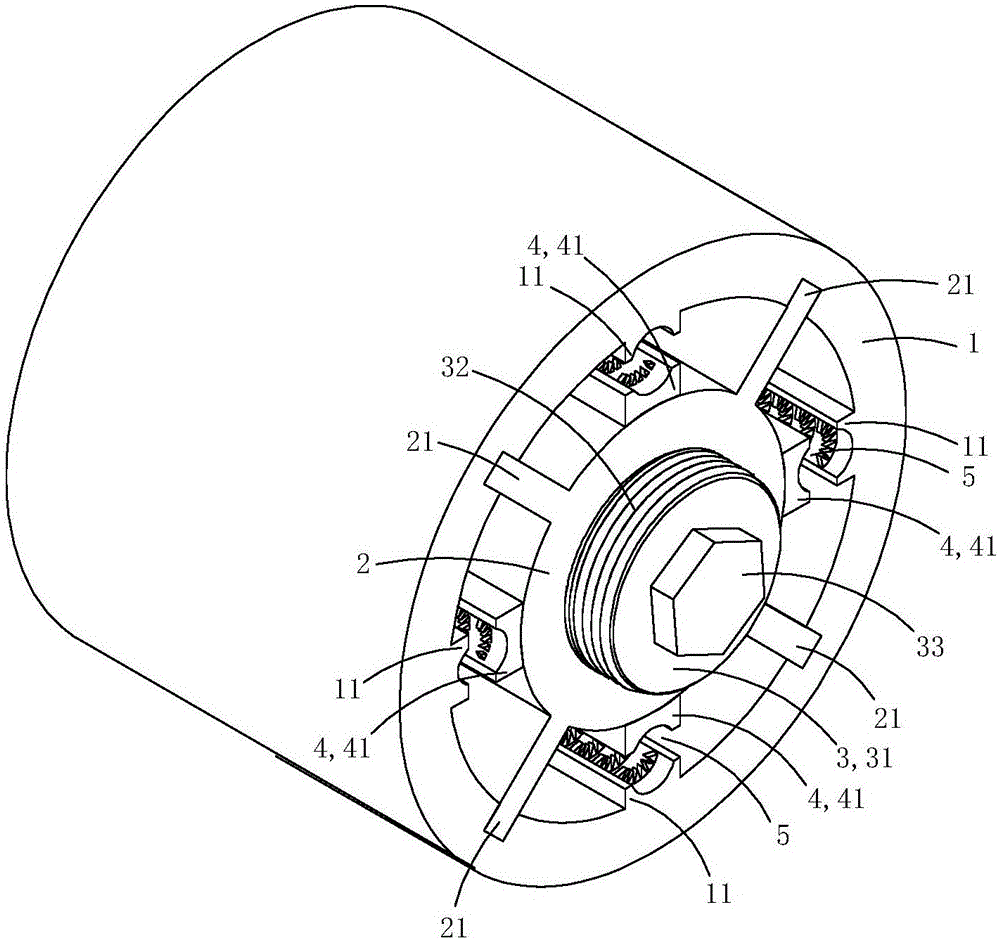
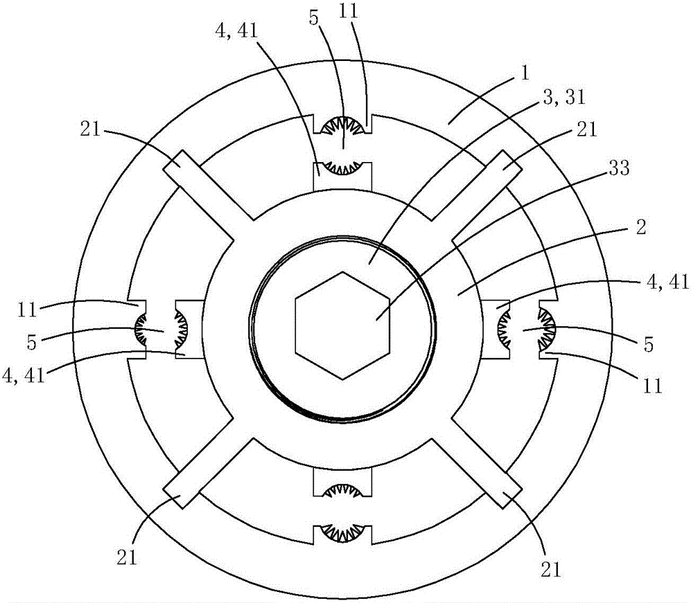
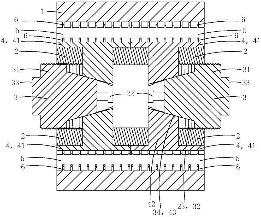
[0021] This embodiment is an improved electric clamping fitting, see Figure 1 to Figure 5 As shown, it includes a base tube 1 , a core tube 2 , two crimping parts 3 and two sets of crimping jaw assemblies 8 .
[0022] The inner peripheral wall of the base pipe is provided with four clamping bosses 11, and the inner wall of each clamping boss is provided with arc-shaped grooves 111, and each wire-holding boss and arc-shaped grooves extend axially along the base pipe. The inner peripheral wall of the base pipe is also provided with a plurality of positioning sliding grooves 12 along the axial direction of the base pipe.
[0023] The core tube and the base tube are concentrically arranged, and the core tube is located in the lumen of the base tube; the outer peripheral wall of the core tube is provided with four supporting convex plates 21 protruding radially along the base tube, and the outer ends of each supporting convex plate are located at corresponding A positioning chute...
Embodiment 2)
[0035] This embodiment is basically the same as Embodiment 1, the difference is: see Image 6 with Figure 7 As shown, the base pipe 1 is provided with a mounting screw hole 18 that penetrates the wall of the clamping boss 11 along the radial direction of the base pipe; a temperature sensing device 8 is fixed in the mounting screw hole;
[0036] The temperature sensing device includes a metal housing 81 made of metal material with a containing groove 811, a temperature sensor 82 arranged in the containing groove, a spring 83 for crimping the temperature sensor on the bottom wall of the containing groove, Coil plug 84 for limit spring;
[0037] One end 812 of the metal shell close to the central axis of the base tube is provided with a heat conduction boss 813 used as a puncture, and one end 814 of the metal shell away from the central axis of the base tube is provided with an inner hexagonal screw groove 815; There is an external thread 816 adapted to the mounting screw hole...
Embodiment 3)
[0045] This embodiment is basically the same as Embodiment 2, the difference is: see Figure 8 As shown, this embodiment also includes a current transformer 7; the current transformer includes an annular induction body 71 and an intelligent control module 72; in this embodiment, the intelligent control module 72 is made into a ring with the same size cavity as the annular induction body Shaped, ring-shaped inductive induction body and intelligent control module are arranged side by side to form a ring shape, and the current transformer is integrally sleeved and fixed on the outer peripheral wall of the base pipe. In practice, the current transformer can also be fixedly arranged on the tube wall of the core tube, as long as all the clamping holes are located in the cavity of the ring-shaped induction body, that is, it is only necessary to make the cable pass through the hole of the ring-shaped induction body The cavity is enough.
[0046] The intelligent control module may inc...
PUM
 Abstract
Description
Claims
Application Information
 - R&D
- Intellectual Property
- Life Sciences
- Materials
- Tech Scout
- Unparalleled Data Quality
- Higher Quality Content
- 60% Fewer Hallucinations
Browse by: Latest US Patents, China's latest patents, Technical Efficacy Thesaurus, Application Domain, Technology Topic, Popular Technical Reports.
© 2025 PatSnap. All rights reserved.Legal|Privacy policy|Modern Slavery Act Transparency Statement|Sitemap|About US| Contact US: help@patsnap.com