Minimum power distribution area-based distributed feeder automation device arrangement method

A technology for feeder automation and power distribution area, applied in circuit devices, electrical components, information technology support systems, etc., to achieve the effect of simple device design, practical and reliable device design

Inactive Publication Date: 2016-11-09
STATE GRID CORP OF CHINA +4
View PDF3 Cites 4 Cited by
  • Summary
  • Abstract
  • Description
  • Claims
  • Application Information

AI Technical Summary

Problems solved by technology

[0003] The technical problem to be solved by the present invention is to provide a distributed feeder automation device configuration method based on the minimum power distribution area that can effectively solve the problem of rapid fault location and isolation in the case of distributed power supply access or ring network operation

Method used


Image

  • Minimum power distribution area-based distributed feeder automation device arrangement method
  • Minimum power distribution area-based distributed feeder automation device arrangement method
  • Minimum power distribution area-based distributed feeder automation device arrangement method

Examples


Embodiment 1

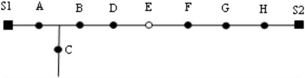
[0072] Such as figure 1 In the distribution network shown, when the system is running in open loop, if a fault occurs in the BD section of the switch, the action steps of each distributed feeder automation device are as follows:

[0073] The feeder automation device at the switch S1 in the smallest power distribution area can know that the fault current flows through the acquisition unit, and the direction of active power is from the switch to the area S1A, so VN S1 = 1, through the communication unit, it can be known that switch A in the adjacent minimum power distribution area experiences fault current, and the direction of active power is to flow out of area S1A, so VN S11 =0, it can be seen from the formula (2) in the calculation unit that Vgroup S11 ={1&&0}=0, so A S1 =0, switch S1 does not act. Do not start the control unit.

[0074] From the sampling unit of the feeder automation device at switch A in the minimum power distribution area adjacent to switch S1, it can...

Embodiment 2

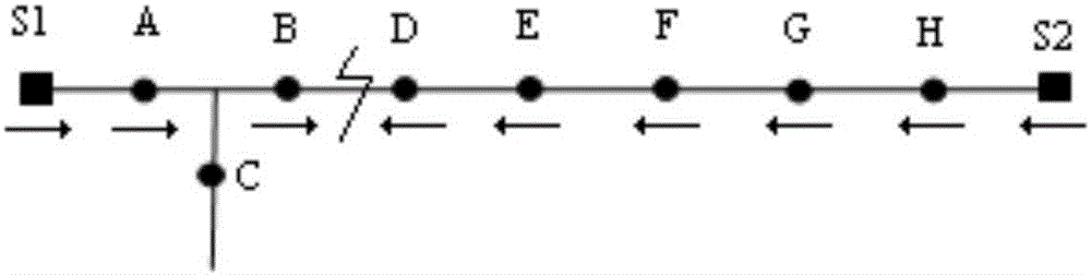
[0081] When the system operates in closed loop, forfigure 1 In the distribution network shown, if a fault occurs in the switch BD section, switches S1, A, B, D, E, F, G, H, and S2 all experience a fault current, and switch C does not experience a fault current. The fault active power flow direction is as follows: figure 2 As shown, the action steps of each distributed feeder automation device are:

[0082] The analysis of switches S1, A, and C is exactly the same as that of the open-loop operation, and will not be repeated here.

[0083] From the sampling unit of the feeder automation device at switch B, it can be known that it has experienced a fault current. It can be seen from the communication unit and calculation unit at switch B that for the first adjacent switch group ABC at switch B, the logic value of switch A is 1, the logic value of switch B is 0, and the logic value of switch C is 1. Logical value Vgroup of an adjacent group B1 is 0; for the second adjacent swi...


PUM


Abstract

The invention discloses a minimum power distribution area-based distributed feeder automation device arrangement method. A distributed feeder automation device is divided into a collection unit, a setting unit, a display unit, a communication unit, a calculation unit, a control unit and a storage battery unit, wherein the collection unit is used for collecting voltage and current of switches in minimum power distribution areas, and power flowing through the switches; the setting unit is used for carrying out parameter setting on equipment, limit values and operation modes in the adjacent minimum power distribution areas; the display unit is used for displaying information collected by the collection unit and parameters set by the setting unit; the communication unit communicates with the feeder automation device in upstream and downstream adjacent minimum power distribution areas and communicates with a master station system or a substation system; the calculation unit is used for obtaining information from the collection unit and the communication unit and analyzing current switch action states; the control unit is used for controlling the states of the switches in the minimum power distribution areas according to the calculation result of the calculation unit; and the storage battery unit is used for supplying the distributed feeder automation device with electricity. By the minimum power distribution area-based distributed feeder automation device arrangement method, rapid location and isolation of faults under the condition of connection of a distributed power supply or loop network operation can be effectively achieved.

Description

technical field [0001] The invention relates to a distribution network feeder automation device. In particular, it relates to a distributed feeder automation device configuration method based on the minimum power distribution area. Background technique [0002] As an important part of distribution network automation, the feeder automation system has the function of isolating faulty areas and quickly restoring power supply to healthy areas. It is of great significance to reduce the blackout area, shorten the blackout time, and improve the reliability of power supply. Distributed feeder automation system is a method that relies on the mutual cooperation between equipment to isolate faults and restore power to healthy areas. According to the way of fault isolation, it can be divided into switch coordination type feeder automation and "surface protection" type feeder automation. Switch-coordinated feeder automation does not require communication, relying only on the mutual co...

Claims


Application Information

Patent Timeline
Patent Type & Authority Applications(China)
IPC IPC(8): H02J13/00
CPCH02J13/0006Y02E60/00Y04S10/16
Inventor 宋璇坤韩柳徐弢李军王伟胡殿刚于建成宋宁希张小敏段军红吴磊肖智宏黄飞彭竹弈徐昊亮庄博靳攀润高涵王笑雪
Owner STATE GRID CORP OF CHINA
Why Eureka
Try Eureka