

Boom system for a mobile crane, and mobile crane
A technology for moving cranes and cranes, applied in the direction of cranes, etc., can solve the problems affecting the maximum length of the telescopic cantilever, and achieve the effect of improving the connection rigidity, reducing the load, and reducing the load
- Summary
- Abstract
- Description
- Claims
- Application Information
AI Technical Summary
Problems solved by technology
Method used
Image

Examples
Example Embodiment
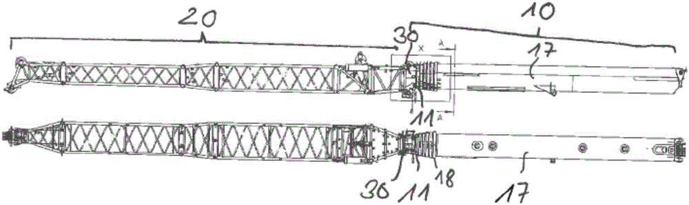
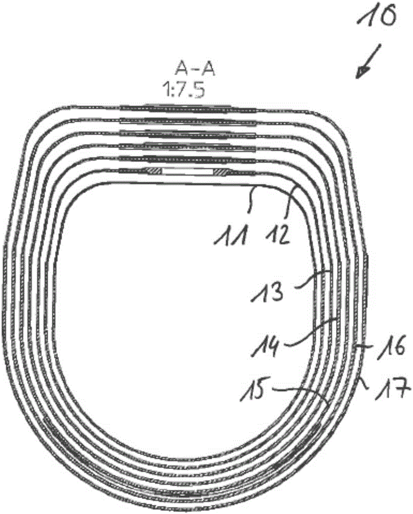
[0036] figure 1The boom system according to the invention is shown in side view and plan view. The cantilever system consists of a telescopic main cantilever 10 and a pointed cantilever in the form of a pivotable truss-like tip 20 fastened thereto by means of bolts. The telescopic jib 10 consists of a total of seven telescopic tube eyelets 11, 12, 13, 14, 15, 16, 17, which are usually mutually supported alternately via support elements. These support elements are fastened from the inside to rims 18 of the telescopic tube eyelets 11 to 17 arranged on the end faces. This telescoping process is carried out by telescoping cylinders, not shown.
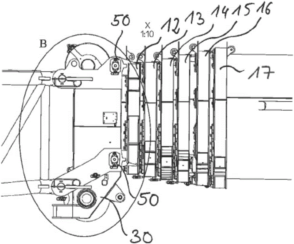
[0037] exist image 3 The connection position in the region X between the pointed cantilever 20 and the main cantilever 10 is shown in . It can be seen that the central telescopic tube eye 11 has a roller tip 30 on the end side, to which end the pointed suspension 20 is fastened by means of a four-point screw.
[0038] According to th...
PUM
 Abstract
Description
Claims
Application Information