Water jet propeller apparatus for a personal watercraft

a propeller and water jet technology, applied in the field of personal watercraft water jet propeller apparatus, can solve the problems of undesirable corrosion of the impeller shaft surface, prohibitive cost of this corrosion-inhibiting material, and water leakage through a gap, so as to reduce the problem of corrosion and minimize the effect of water intrusion through the impeller sha

Active Publication Date: 2005-03-29
HONDA MOTOR CO LTD
View PDF3 Cites 5 Cited by
  • Summary
  • Abstract
  • Description
  • Claims
  • Application Information

AI Technical Summary

Benefits of technology

The present invention provides a water jet propeller apparatus that reduces the corrosion problems that were experienced in the prior art. A water jet propeller apparatus a

Problems solved by technology

There is a problem with the design of this reference, in that water may leak in through a gap between the front edge 4a of the collar 4 and the rear edge 2a of the impeller 2.
After leaking through the aforementioned

Method used


Image

  • Water jet propeller apparatus for a personal watercraft
  • Water jet propeller apparatus for a personal watercraft
  • Water jet propeller apparatus for a personal watercraft

Examples


first embodiment

Shock-Absorbing Member-First Embodiment

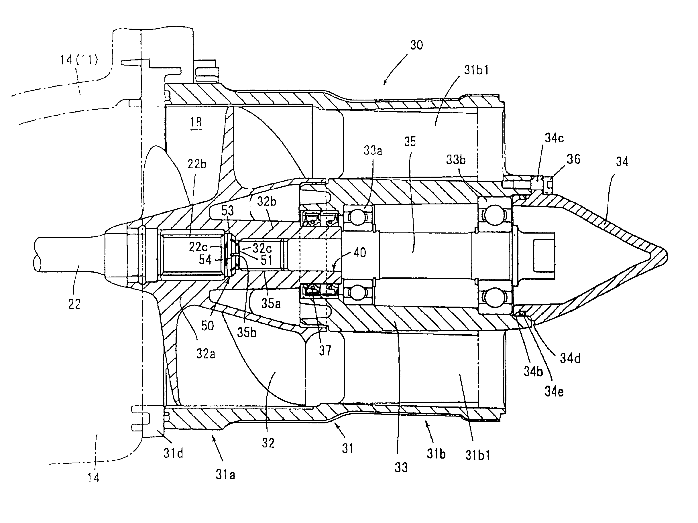
A shock-absorbing member 50 may also be provided in the impeller boss 32a between the front end 35b of the impeller shaft 35 and the rear end 22c of the drive shaft 22, for cushioning the rear tip end 22c of the drive shaft. The shock-absorbing member 50 may be formed of rubber or from a suitable water-resistant elastomer. The shock-absorbing member 50 may be provided with a convex front face 59, as shown, to contact and cushion the rear tip end 22c of the drive shaft 22.

The outer periphery of the shock-absorbing member 50 is configured to allow fluid(s) such as air and / or grease to flow therepast, from the impeller shaft 35 side toward the drive shaft 22 side, when the impeller shaft 35 is assembled to the impeller boss 32a.

FIGS. 4(a) and 4(b) are drawings showing a shock-absorbing member 50 according to a first embodiment thereof, in which FIG. 4(a) is a rear plan view of the shock absorbing member taken from a vantage point behind the vesse...

second embodiment

Shock-Absorbing Member-Second Embodiment

FIGS. 5(a) and 5(b) are drawings showing a modified version of the shock-absorbing member according to a second embodiment thereof, in which FIG. 5(a) is a rear plan view of the shock absorbing member taken from a vantage point behind the vessel body, and FIG. 5(b) is a side view thereof.

The shock-absorbing member 150 may be provided with a convex front face 159, as shown, to contact and cushion the rear tip end 22c of the drive shaft 22.

A shock-absorbing member 155, according to the embodiment of FIG. 5, is formed in such a manner that a large-diameter sealing portion 156, that comes into intimate contact with the inner peripheral surface of the impeller boss 32a, is formed with at least one ring-shaped thin sealing lip 157 thereon, so that a fluid such as air or grease can easily be released toward the drive shaft 22.

In this arrangement, when the impeller shaft 35 is fastened to the impeller boss 32a, air (or grease) between the front end 35...


PUM

PropertyMeasurementUnit
Diameteraaaaaaaaaa

Abstract

A jet pump for a personal watercraft is designed to prevent water from contacting an impeller shaft therein. The apparatus includes a stator 31 with a channel 18 formed therein. An impeller 32 and an impeller shaft 35 are rotatably disposed in the stator 31, and are connected to one another by a threaded connection therebetween. A collar 40 is integrally formed with the impeller 32, and a water-resistant seal 37 is provided between the collar 40 and the stator. The impeller shaft 35 is constructed so that a drive shaft 22 is connectable to the front thereof by a spline fit. A shock-absorbing member 50 is provided for placement between the impeller shaft and the drive shaft, and the shock-absorbing member includes structure adapted to allow air or grease to pass toward the drive shaft side thereof, when the impeller is screwed on to the impeller shaft.

Description

BACKGROUND OF THE INVENTION1. Field of the InventionThe present invention relates to a water jet propeller apparatus for a vessel, such as a personal watercraft. More particularly, the present invention relates to a water jet-propeller apparatus in which an impeller and an impeller shaft are joined in a manner such that water intrusion via the impeller shaft is minimized, and a corrosive effect on the impeller shaft is reduced, due to its limited exposure to the water being propelled by the impeller.2. Description of the Background ArtA small waterboat, or personal watercraft, is a small size craft that is constructed and arranged to glide under power across the surface of a sea or of a lake. Many jet skis and other different types of personal watercraft are known and are commercially available.In the art relating to personal watercraft, some designs for water jet propellers are known. For example, FIG. 6 hereof is a reproduction of one of the drawings from Japanese utility Model Re...

Claims


Application Information

Patent Timeline
IPC IPC(8): B63H11/00B63H23/32B63H23/34B63H23/00B63H11/08F16F1/36F16F1/377F16F1/373B63B35/73
CPCB63H11/08B63H23/321B63H23/34F16F1/377F16F1/3732B63H2023/327B63H2011/081
Inventor FUSE, TOMOHIRO
Owner HONDA MOTOR CO LTD
Why Eureka
Try Eureka