Tool positioning-clamping mechanism for milling machine

A tool positioning and clamping mechanism technology, applied in positioning devices, clamping, manufacturing tools, etc., can solve the problems of lower repeat positioning accuracy and tool change accuracy, insufficient connection rigidity, and insufficient clamping effect, etc., to achieve clamping Good effect, good connection rigidity, smooth rotation effect

Inactive Publication Date: 2012-07-18
宁波远达船机配件有限公司
View PDF7 Cites 5 Cited by
  • Summary
  • Abstract
  • Description
  • Claims
  • Application Information

AI Technical Summary

Problems solved by technology

Milling machines generally use metric tapers, but with the continuous improvement of cutting precision, the existing method of using metric tapers as the connection between the milling machine spindle and the tool can no longer meet the new processing requirements. The main problem is that the connection rigidity is not enough, and at high Under the high speed, due to the expansion of the spindle taper hole, the repeated positioning accuracy and tool change accuracy are reduced, and the clamping effect is not good enough

Method used


Image

  • Tool positioning-clamping mechanism for milling machine
  • Tool positioning-clamping mechanism for milling machine
  • Tool positioning-clamping mechanism for milling machine

Examples


Embodiment Construction

[0016] The following combined with the attachment of the present invention is further explained in detail.

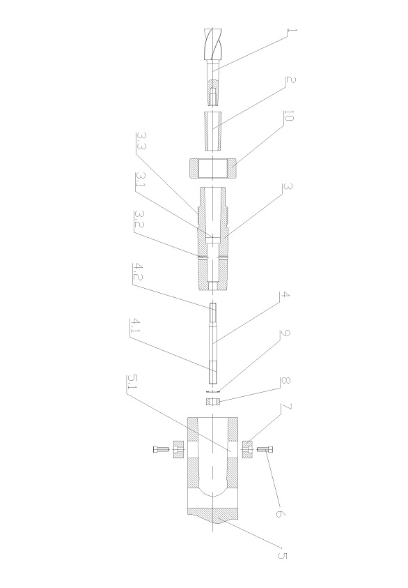
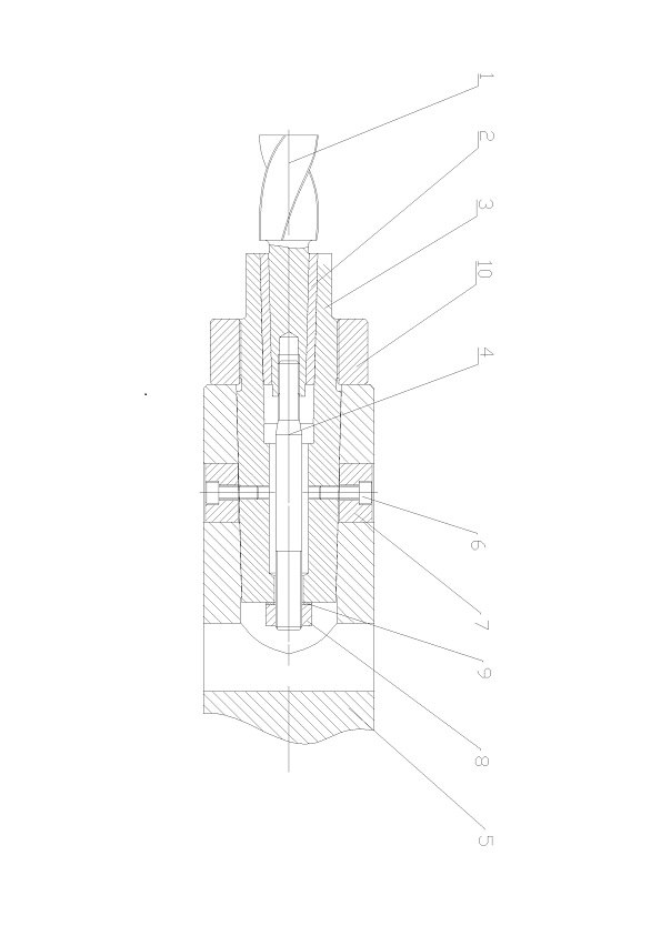
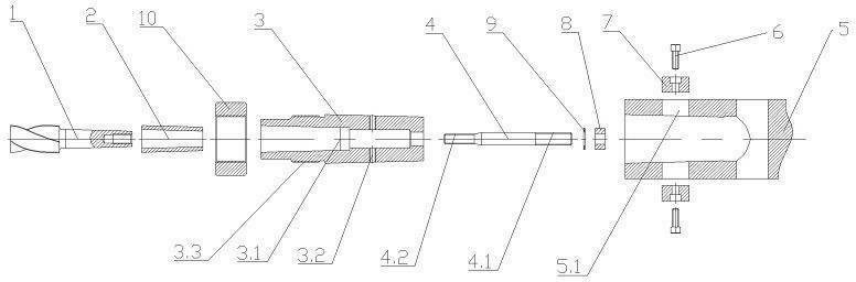
[0017] like figure 1 and 2 Show, a tool positioning and clamping mechanism for milling machines, including knife 1, knife handle body 3, and lever 4.And fixed with the main axis 5 of the machine tool, the handle body 3 is closely fitted with the main axis of the machine tool, the handle body 3 has a central hole 3.1, the tool 1 package is within the center hole 3.1, the lever 4 is set in the center hole 3.1, the lever 4 is 4One end is connected to the handle body 3, and the other end of the lever is connected to the tool 1.

[0018] The knife handle 3 and the main axis of the machine tool 5 are fixed. The main axis of the machine tool 5 is equipped with radial pores 5.1 on the peripheral surface of the outer surface of the machine, and the handle body 3 has the first thread corresponding to the radial pores 5.1 positionPole 3.2, including bolts 6 and waist key 7 for embedde...


PUM


Abstract

The invention discloses a tool positioning-clamping mechanism for a milling machine, which comprises a tool (1), a tool shank (3) and a pull bar (4). The tool shank (3) is partially contained in a machine spindle (5) and fixed to the same, the tool shank (3) is provided with a center hole (3.1), the tool (1) is nested into the center hole (3.1), the pull bar (4) is contained in the center hole (3.1), one end of the pull bar (4) is connected with the tool shank (3) and axially limited, the other end of the pull bar (4) is fixedly connected with the tool (1), and accordingly the tool (1) is fixedly connected with the machine spindle (5). The connection way is higher in connection rigidity than the original Morse taper connection way, connection is more stable, and clamping is better. When the machine spindle is in high-speed rotation, the tool is more stable in rotation and less apt to fall from the spindle, and safety factor is higher.

Description

Technical field [0001] The present invention involves the field of machine tool processing. Specifically, a tool positioning mechanism for milling machines is used. Background technique [0002] At present, when machining the cylinder head, it is necessary to use milling machines for processing. The tool and the main axis of the milling machine for milling machines is mainly based on Mo's conical clamping positioning. Mo's conicalness is an international standard of a taper.Because the taper is very small, it can pass a certain torque and because of the taper, so it is easy to disassemble. Mo's conicalness uses the principle of friction. In a certain cone range, the workpiece can be freely disassembled.Milling machines generally use public taper, but as the accuracy of cutting processing continues to improve, the existing public taper as the method of connecting the spindle of the milling machine is no longer able to meet the new processing requirements.At the speed, due to the e...

Claims


Application Information

Patent Timeline
Patent Type & Authority Applications(China)
IPC IPC(8): B23Q3/12
Inventor 刘海军
Owner 宁波远达船机配件有限公司
Why Eureka
Try Eureka