Packing for substrate plating jig and the substrate plating jig using same

A substrate and gasket technology, applied in the field of gaskets for plating fixtures, can solve problems such as damage to the sealing effect, step difference, etc., and achieve the effects of high sealing effect, low manufacturing cost, and high elastic strength

Inactive Publication Date: 2016-11-09
JCU CORP
View PDF7 Cites 2 Cited by
  • Summary
  • Abstract
  • Description
  • Claims
  • Application Information

AI Technical Summary

Problems solved by technology

[0007] However, the substrate plating jig fixes the substrate pressing portion to the substrate support portion in a crimped state when clamping the substrate, and releases the crimping when attaching or detaching the plated substrate. Pressing and depressing at the joint part of the part end, if the fixation at the joint end is not properly performed, a gap or a step difference will be generated at the seam of the joint part, and there is a possibility of impairing the sealing effect

Method used


Image

  • Packing for substrate plating jig and the substrate plating jig using same
  • Packing for substrate plating jig and the substrate plating jig using same
  • Packing for substrate plating jig and the substrate plating jig using same

Examples


Embodiment Construction

[0027] Hereinafter, embodiments of the gasket for a plating jig of the present invention and a plating jig using the same will be described in detail based on the drawings. In addition, the present invention is not limited by these embodiments.

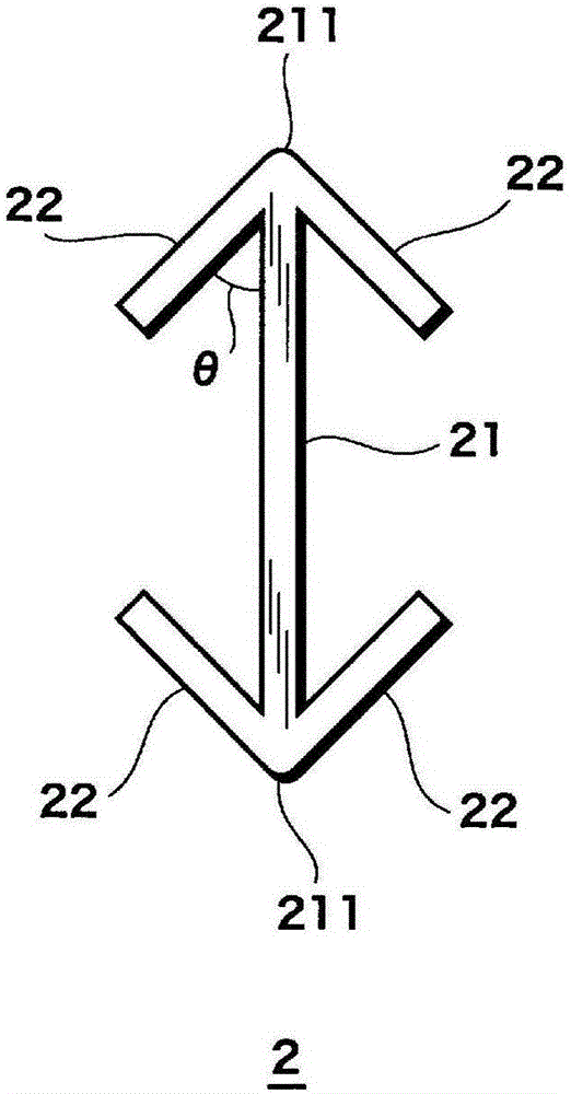
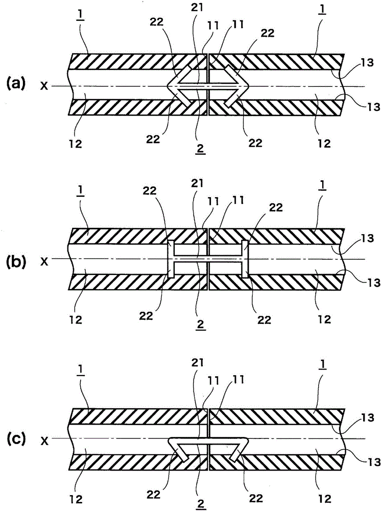
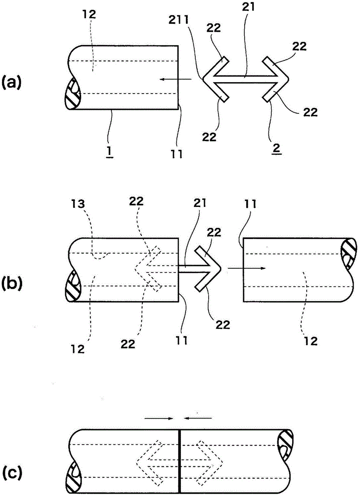
[0028] The gasket of the present invention is a tubular or rope-shaped gasket body 1 formed of a long strip of elastic material with ends, and a connection for connecting the two ends of the gasket body 1 (hereinafter referred to as "connection ends"). Component 2 is constructed. The pad main body 1 is preferably manufactured by extrusion molding which is also advantageous in terms of manufacturing cost, but the manufacturing method is not limited thereto. The two connection ends of the gasket main body 1 are connected and fixed to each other by the connection member 2, so that it can be used as an endless ring or quadrangular or other shaped sealing member. Thereby, since it is originally a single end member, it is possible to arbi...


PUM


Abstract

The problem addressed by the present invention is providing packing for a substrate plating jig that is more advantageous in terms of cost than O-rings and can handle various dimensions and shapes for a substrate jig and the substrate plating jig that uses the packing. The packing is attached to the plating jig and is for sealing conductive members for electrifying the substrate and parts of the substrate surface in contact with the conductive members from plating fluid. The packing is provided with a packing main body formed from an elastic material that has an elongated shape and an end, and a connecting member for making a non-ending shape by connecting and affixing connecting ends of both end parts of the packing main body to each other. The connecting member is formed from a shaft part and a plurality of hooks provided so as to protrude at a prescribed angle from the shaft part. The connecting member is provided inside and extends within the packing main body in both directions from the connecting point within a prescribed range so as to extend over the connecting point where the connection ends are linked when the two ends of the packing main body are linked.

Description

technical field [0001] The present invention relates to a pad for a plating jig used for plating a substrate and a jig using the same. Background technique [0002] The plating jig used in the electrolytic plating method generally includes sealing the peripheral part of the substrate such as a semiconductor wafer and the part in contact with the current-carrying parts, and exposing and holding the surface of the substrate or the surface to be plated on the front and back sides. In order to be a detachable substrate holder, the substrate holder is immersed in a plating solution together with the substrate to plate the surface to be plated of the substrate. [0003] In this way, when the substrate holder is immersed in the plating solution together with the substrate, in order to protect the conductive member for energizing the substrate and the substrate surface portion in contact with the conductive member from contacting the plating solution, the A packing (packing) as a s...

Claims


Application Information

Patent Timeline
Patent Type & Authority Applications(China)
IPC IPC(8): C25D17/06
CPCC25D17/06C25D17/001C25D17/005C25D17/004
Inventor 村山隆史
Owner JCU CORP
Why Eureka
Try Eureka