Toroidal continuously variable transmission

A continuously variable transmission, annular technology, used in couplings, rigid shaft couplings, friction transmission devices, etc., can solve the problems of lubricating oil pollution and poor lubrication state, and achieve the effect of improving support rigidity

Active Publication Date: 2016-11-09
NSK LTD
View PDF12 Cites 0 Cited by
  • Summary
  • Abstract
  • Description
  • Claims
  • Application Information

AI Technical Summary

Problems solved by technology

Fretting wear may become the starting point of damage such as peeling, or the generated wear powder may contaminate the lubricating oil (traction oil), resulting in poor lubrication of each part

Method used


Image

  • Toroidal continuously variable transmission
  • Toroidal continuously variable transmission
  • Toroidal continuously variable transmission

Examples


Embodiment Construction

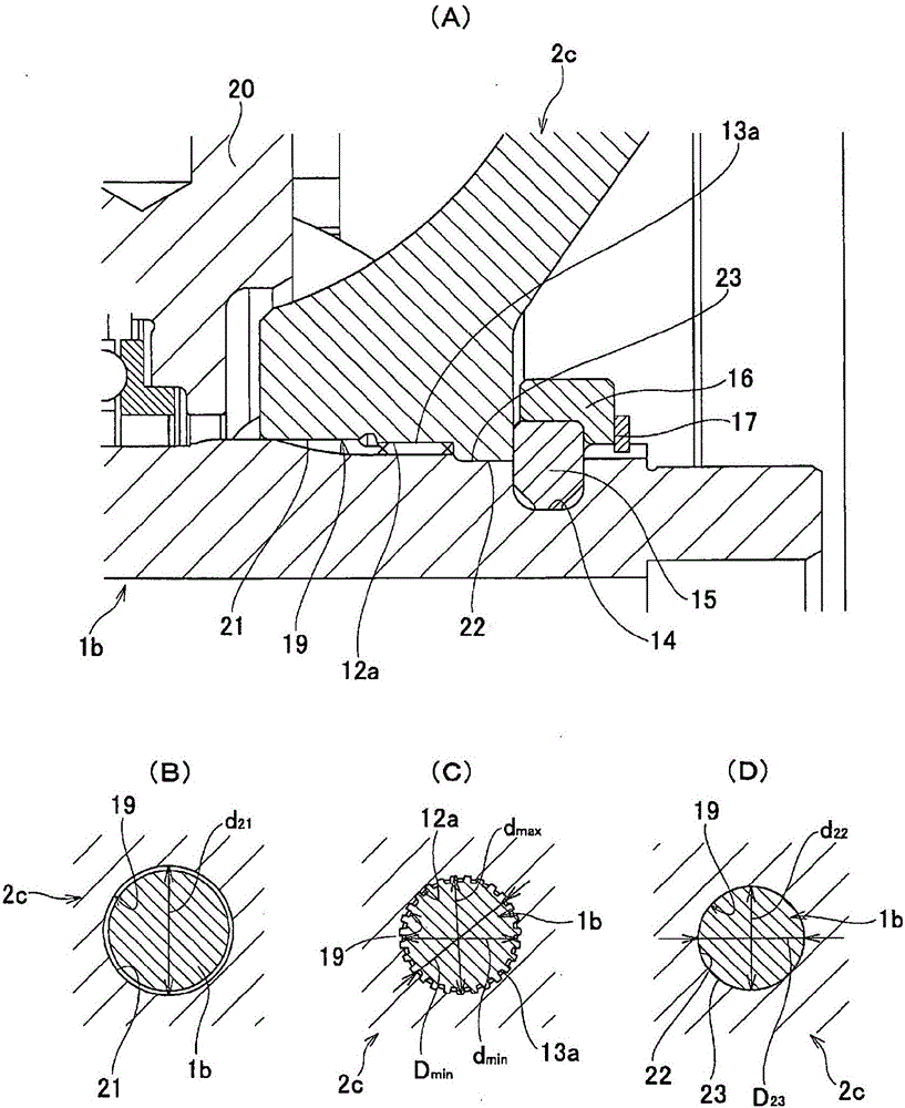
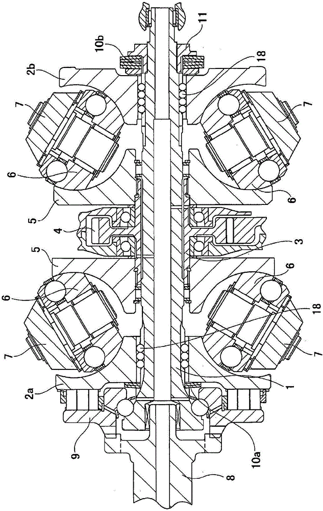
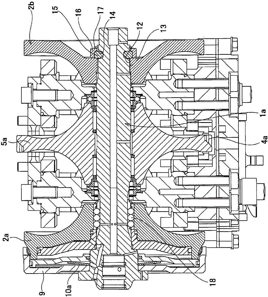
[0041] figure 1 An example of an embodiment of the toroidal continuously variable transmission of the present invention is shown. In this case the toroidal continuously variable transmission with Figure 3 ~ Figure 6 The second example of the conventional toroidal continuously variable transmission shown similarly includes an input rotating shaft 1b as a rotating shaft, a pair of input side discs 2a, 2c as a pair of outer discs, an output side disc 5a as an inner disc, multiple A trunnion 7 as a supporting member, a plurality of power rollers 6, a pressing device 9a, and a locking ring 15 as a locking member.

[0042] The pair of input disks 2a and 2c is composed of one input disk 2a disposed around one end of the input shaft 1b and the other input disk 2c disposed around the other end of the input shaft 1b. The one input side disk 2 a and the other input side disk 2 c each have an axially one side surface facing axially inward of the input rotary shaft 1 b as a circular cu...


PUM


Abstract

In order to prevent fretting wear based on elastic deformation in the axial direction of an input-side disk (2c) due to the thrust force of a pressing device, female spline parts (13a), which are formed in the middle section in the axial direction in the inner circumferential surface of a center hole (19) of an input-side disk (2c), and male spline parts (12a), which are formed in the outer circumferential surface at one end in the axial direction of an input rotary shaft (1b), are spline coupled to each other, and a disk-side mating surface part (22), which is formed at the portion of the inner circumferential surface of the center hole (19) which is adjacent to the other end of the female spline parts (13a), and a shaft-side mating surface part (23), which is formed at the portion of the outer circumferential surface of the input rotary shaft (1b) which is adjacent to the other end of the male spline parts (12a), are mated to each other with an interference fit.

Description

technical field [0001] The present invention relates to a toroidal continuously variable transmission used as a transmission for automobiles or a transmission for adjusting the operating speed of various industrial machines such as pumps. Background technique [0002] Japanese Patent Application No. 2003-214516, Japanese Patent Application No. 2007-315595, Japanese Patent Application No. 2008-25821, Japanese Patent Application No. 2008-275088, etc. The semi-toroidal continuously variable transmission is used as a speed changer for automobiles. device. In addition, Japanese Patent Application Laid-Open No. 2004-169719 and the like describe a structure in which the adjustment range of the gear ratio is enlarged by using a combination of a toroidal continuously variable transmission and a planetary gear mechanism. [0003] figure 2 A first example of a conventional structure of a toroidal continuously variable transmission is shown. In the first example of the conventional s...

Claims


Application Information

Patent Timeline
Patent Type & Authority Applications(China)
IPC IPC(8): F16H15/38F16D1/06F16D1/09
Inventor 福田晃大丰田俊郎西井大树斋藤俊博
Owner NSK LTD
Why Eureka
Try Eureka