A kind of cpu and multi-cpu system management method
A consistent and cross-domain technology, applied in the computer field, can solve problems such as reduced reliability, low reliability, and single cross-NC access path
- Summary
- Abstract
- Description
- Claims
- Application Information
AI Technical Summary
Problems solved by technology
Method used
Image
Examples
Embodiment 1
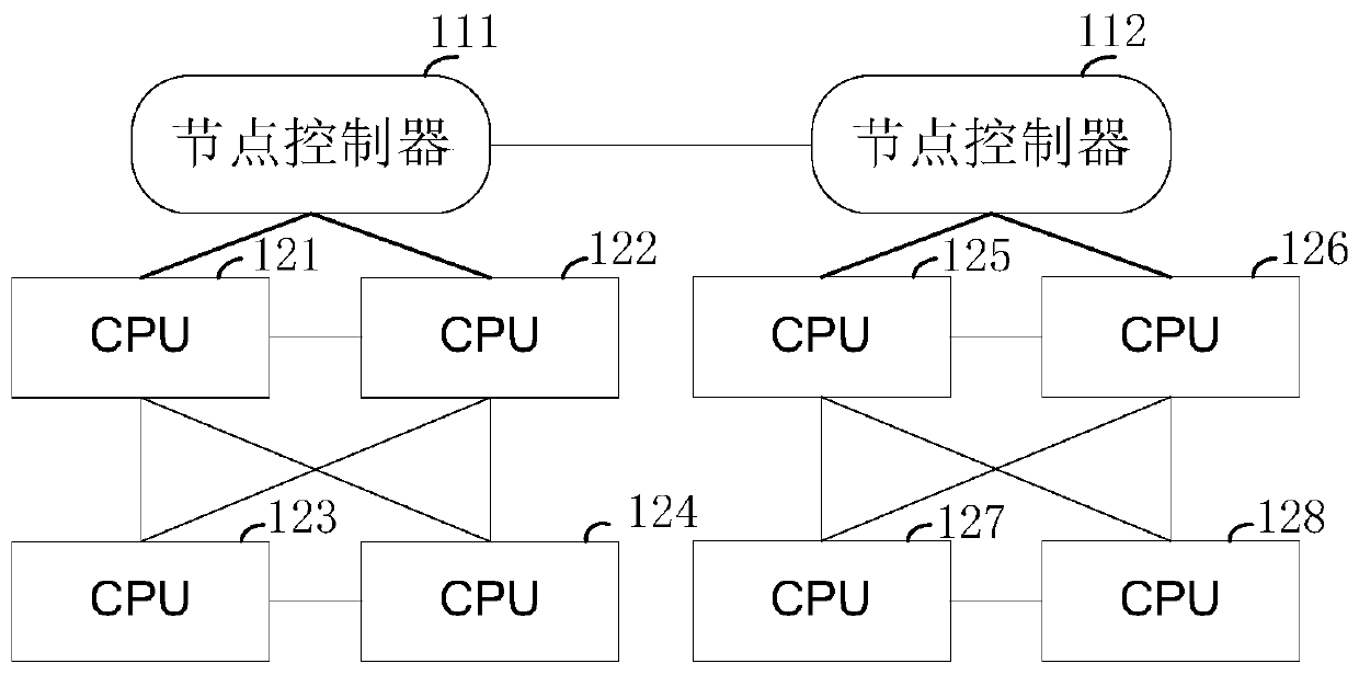
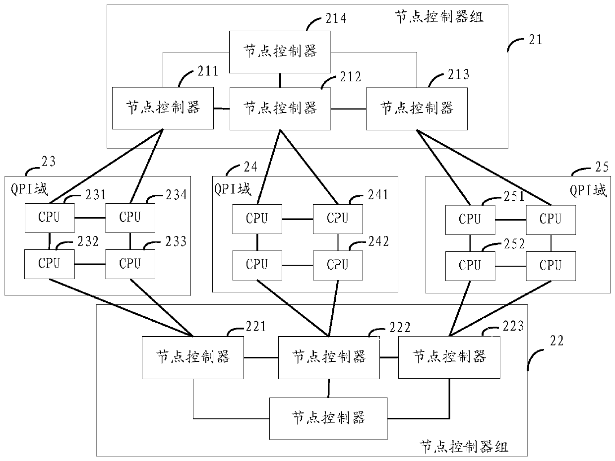
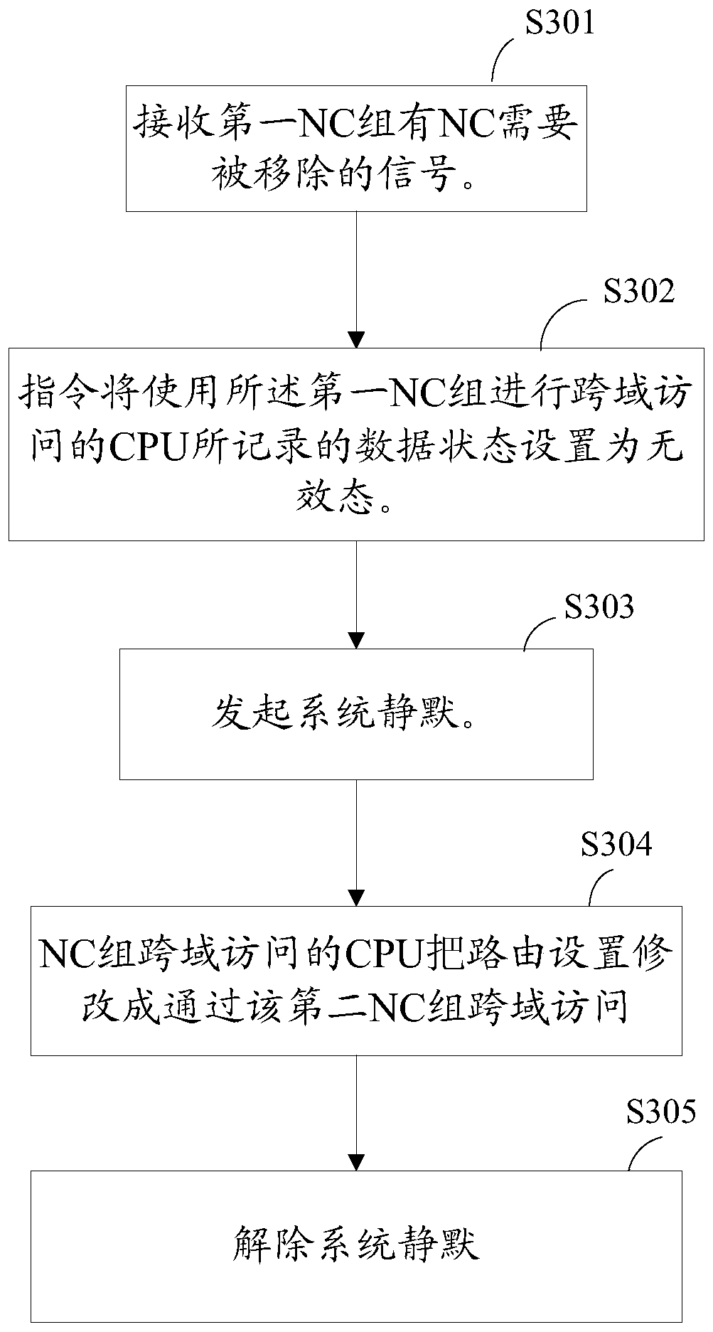
[0056] See attached image 3 , the embodiment of the present invention provides a NC heat removal method, the method is based on the attached figure 2 structure is introduced.
[0057] When the NC preparation in the first NC group is removed, the main CPU controls all CPUs in the multi-CPU system that use the first NC group for cross-domain access, and switch to use the second NC group for cross-domain access .
[0058] Assuming that the main CPU is the CPU 234 in the QPI domain 23, and the NC to be removed is the NC211, for the convenience of description, in this embodiment, the NC 211 to be removed is called the target NC. The NC group 21 is called a first NC group, and the NC group 22 is called a second NC group.
[0059] S301. The main CPU receives a signal that NCs in the first NC group need to be removed.
[0060] For example, when the user is about to remove the NC 211 , the user may send a removal instruction to the main CPU 234 through the operating system, and t...
Embodiment 2
[0098] See attached Figure 4 , the process of adding an NC to an existing NC group is introduced below. still with figure 2 Take the system architecture as an example, where CPU234 is the main CPU. A new NC211 is added to the NC group 21. In order to distinguish it from the removed NC211 in the first embodiment, this embodiment is called another target NC. This embodiment can be performed after the first embodiment, which is equivalent to replacing the NC211. In the case of no special description, some related introductions of the embodiments are used.
[0099] This embodiment can be used to reactivate the first NC group after another target NC is inserted into the first NC group. That is, at least one CPU in the multi-CPU system that uses the second NC group for cross-domain access is controlled to switch to use the first NC group for cross-domain access.
[0100] In step S401, the main CPU detects that another target NC is inserted into the first NC group.
[0101] E...
Embodiment 3
[0136] In the first embodiment, after the target NC is removed, the entire NC group where the target NC is located no longer forwards data. This method has fast switching speed and simple operation.
[0137] see Figure 5 , this embodiment proposes another NC heat removal method. After the target NC is removed, at least one of the remaining NCs in the NC group where the target NC is located can continue to work normally, that is, can perform data forwarding. Compared with the solution in Embodiment 1, the utilization rate of NC is improved. Still referring to the attached figure 2 The framework of the present invention is introduced in detail.
[0138] S501. The main CPU receives a signal that a target NC needs to be removed from the first NC group.
[0139] The target NC is the NC to be removed, which is NC211 in this embodiment. This step is the same as step S301, so it will not be repeated here.
[0140] S502. The main CPU instructs all the CPUs in the multi-CPU syst...
PUM
 Abstract
Description
Claims
Application Information
 - R&D
- Intellectual Property
- Life Sciences
- Materials
- Tech Scout
- Unparalleled Data Quality
- Higher Quality Content
- 60% Fewer Hallucinations
Browse by: Latest US Patents, China's latest patents, Technical Efficacy Thesaurus, Application Domain, Technology Topic, Popular Technical Reports.
© 2025 PatSnap. All rights reserved.Legal|Privacy policy|Modern Slavery Act Transparency Statement|Sitemap|About US| Contact US: help@patsnap.com


