a cooking utensil
A technology for cooking utensils and silos, applied in pressure cookers and other directions, can solve the problems of poor sealing of the inner cover and the inability to achieve cooking effects, and achieve the effects of improving automation, good cooking taste, and improving sealing performance.
- Summary
- Abstract
- Description
- Claims
- Application Information
AI Technical Summary
Problems solved by technology
Method used
Image
Examples
Embodiment 1
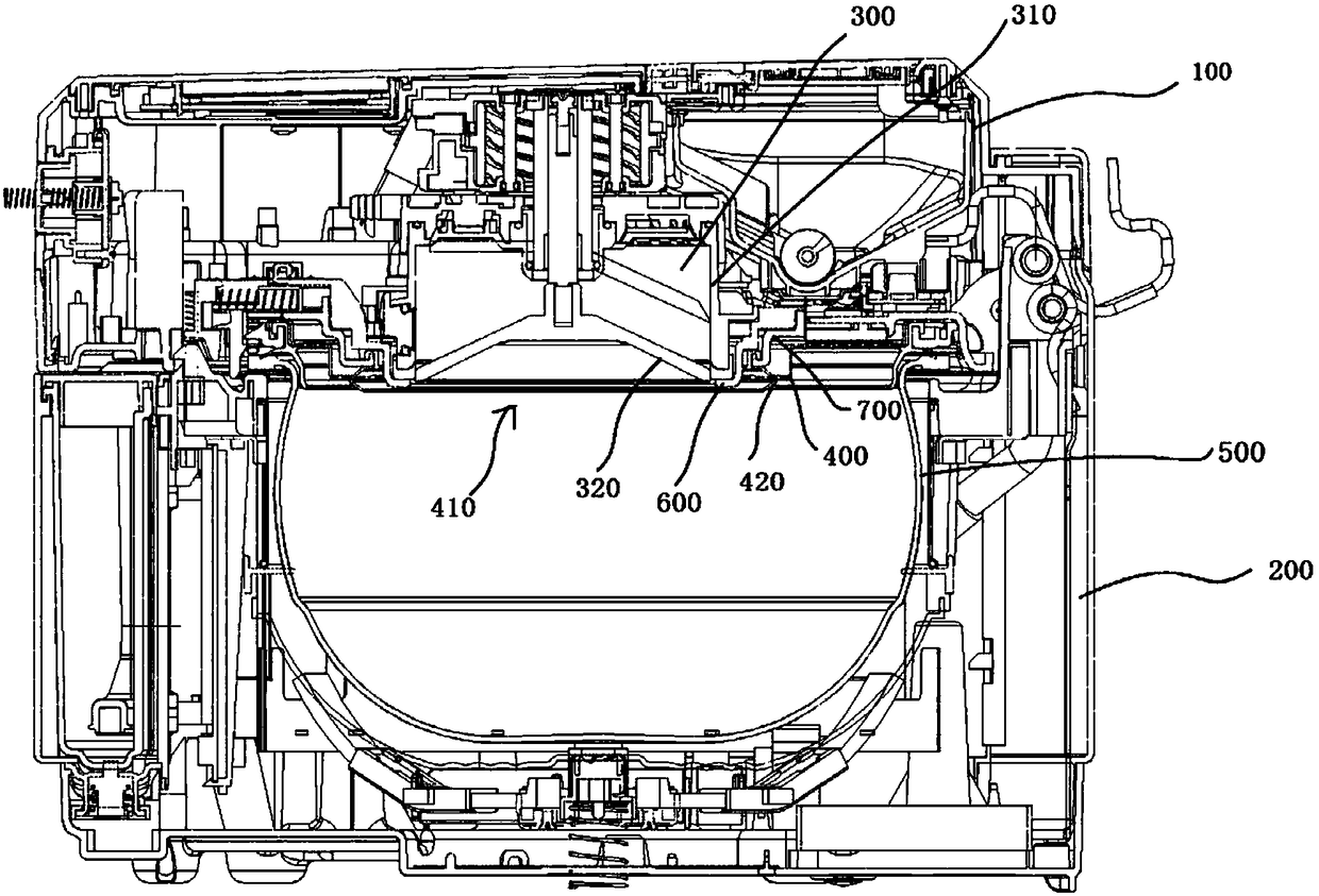
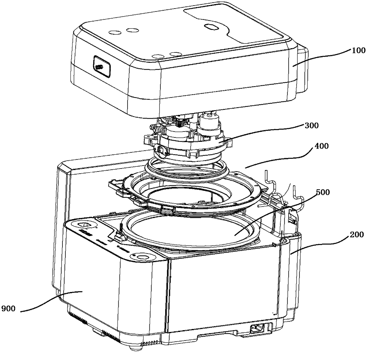
[0035] refer to figure 1 and figure 2 As shown, a cooking utensil includes: a pot cover 100 and a pot body 200, a lower bin assembly arranged on the pot lid 100 and an inner cover 400, the inner cover 400 is arranged under the lower bin assembly, the An inner container 500 is placed in the body of the pot; the inner cover 400 is provided with a feeding hole 410 through which the material in the lowering bin assembly falls into the inner container from the lowering hole; the diameter of the lowering hole is 50-200mm. If the hole diameter of the feeding hole is too large, the overall structure of the inner cover is too large, which further leads to the excessive volume of the whole pot cover 100; The volume of the material is too small to store enough material, and because the hole diameter of the discharge hole is too small, the material is concentrated in the small discharge hole by gravity during the process of releasing the material, resulting in the falling speed of the m...
Embodiment 2
[0040] refer to image 3 as well as Figure 4 As shown, in actual operation, an inner seal 420 used in conjunction with the feeding hole is also provided on the lid 100. When the inner lid 400 is fastened on the lid 100, the inner seal is used to seal In order to achieve a better sealing effect for the gap formed between the lower material bin assembly and the inner cover, this embodiment adopts the first pressing plate 410a formed by extending the edge of the lower material hole to press the inner cover. The sealing member 420 is sealed because when the inner cover is fastened on the lid, one end of the inner cover is inserted into the hinge of the lid, and the other end of the inner cover is buckled on the lid, that is, the whole inner cover faces the direction of the lid Applying axial force, when the inner cover is completely fastened on the lid, the first pressure plate at the inner cover can also exert an axial force on the inner seal, and this axial force can further p...
Embodiment 3
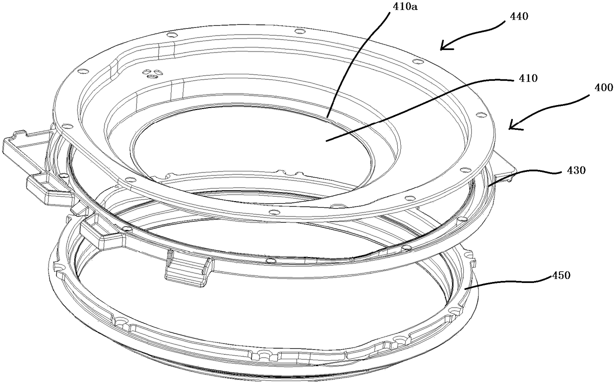
[0050] refer to Figure 7 As shown, in addition to the structure disclosed in Embodiment 1 and Embodiment 2, the structure of the inner cover itself has also been improved as a whole. On the inner surface of the pot cover, the inner cover is provided with an inner step B and an outer step C towards the direction of the lower hopper assembly, and the inner groove formed by the inner step is used to press the lower hopper fixing frame, and the outer step An outer groove is formed to hold down the inner liner.
[0051] Further, the inner step B is composed of a first pressing plate 410a, a second pressing plate 410b parallel to the first pressing plate, and a first connecting plate 410c connecting the first pressing plate and the second pressing plate; the outer step C is composed of the second pressing plate 410b, An upper edge plate 410d parallel to the second pressing plate and a second connecting plate 410e connecting the second pressing plate and the upper edge plate are fo...
PUM
 Abstract
Description
Claims
Application Information
 - R&D
- Intellectual Property
- Life Sciences
- Materials
- Tech Scout
- Unparalleled Data Quality
- Higher Quality Content
- 60% Fewer Hallucinations
Browse by: Latest US Patents, China's latest patents, Technical Efficacy Thesaurus, Application Domain, Technology Topic, Popular Technical Reports.
© 2025 PatSnap. All rights reserved.Legal|Privacy policy|Modern Slavery Act Transparency Statement|Sitemap|About US| Contact US: help@patsnap.com


