Pulse sensor capable of calibrating static force and pulse collection device

An acquisition device and sensor technology, which is applied in the field of medical instruments, can solve the problems of sensor probe displacement, large temperature influence, and poor repeatability of static force, etc., and achieve accurate three-dimensional tactile information acquisition, accurate static force measurement, and dynamic force detection. Effect

Pending Publication Date: 2016-11-16
BEIJING BAIMAIZHILIAN TECH CO LTD
View PDF8 Cites 21 Cited by
  • Summary
  • Abstract
  • Description
  • Claims
  • Application Information

AI Technical Summary

Problems solved by technology

[0008] The patent application CN201420444501 proposed for the first time a pulse collection device combined with multiple types of pressure sensors, which uses a piezoelectric sensor to measure pulse information and a piezoresistive sensor to measure static force. However, the piezoresistive sensor described in this application has no strain The measurement repeatability of structure and static force is poor, it is difficult to achieve accurate calibration, and the measurement of static force cannot meet the high accuracy and standardized measurement required by medical devices
In addition, piezoresistive sensors are made of semiconductor materials, which are greatly affected by temperature, and temperature compensation must be performed when using them.
At the same time, the pulse collection device of this application cannot obtain three-dimensional pulse information
[0009] In addition, during the pulse acquisition process, the collected signal is a contact pressure signal. Since the subject cannot remain still for a long time during the pulse acquisition process, the pressure brought into the wrist by the subject's body posture adjustment Any weak jitter is very likely to cause the sensor probe to shift or break away from the tested point, resulting in a large deviation in the measurement results

Method used


Image

  • Pulse sensor capable of calibrating static force and pulse collection device
  • Pulse sensor capable of calibrating static force and pulse collection device
  • Pulse sensor capable of calibrating static force and pulse collection device

Examples


Embodiment 1

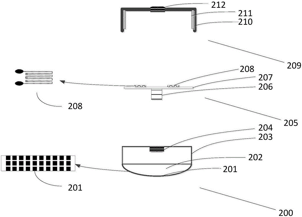
[0043] figure 2 It is a structural schematic diagram of a pulse sensor combined with a strain sensor and a flexible array sensor. Among them, the flexible array sensor is a dynamic force sensor, and the strain sensor is a static force sensor.

[0044] Specifically, the pulse condition sensor includes a flexible array sensor 200 , a strain sensor elastic body 205 and a strain sensor housing 209 . Wherein, the flexible array sensor 200 includes a flexible sensor film 201 , a soft filler 202 and a flexible array sensor housing 203 .

[0045] The flexible sensor film 201 is arranged at the bottom of the flexible array sensor housing 203, and a plurality of pressure-sensing contact points are distributed on the flexible sensor film 201. When in use, the flexible sensor film 201 is attached to the wrist of the human body to perform dynamic force and three-dimensional tactile information. Measurement. Implementations of the flexible sensor film 201 include PVDF films, piezoelectr...

Embodiment 2

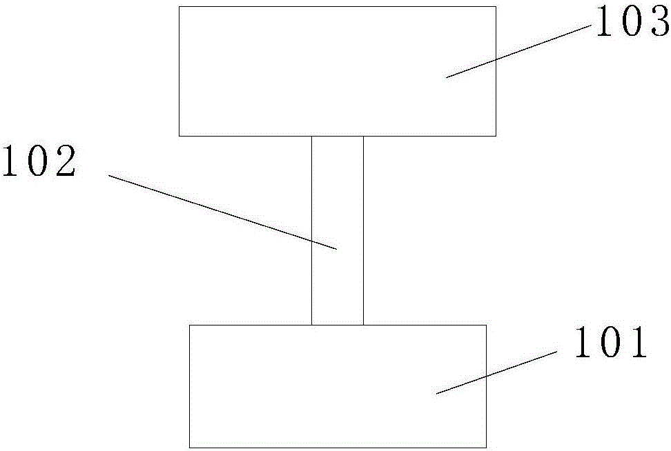
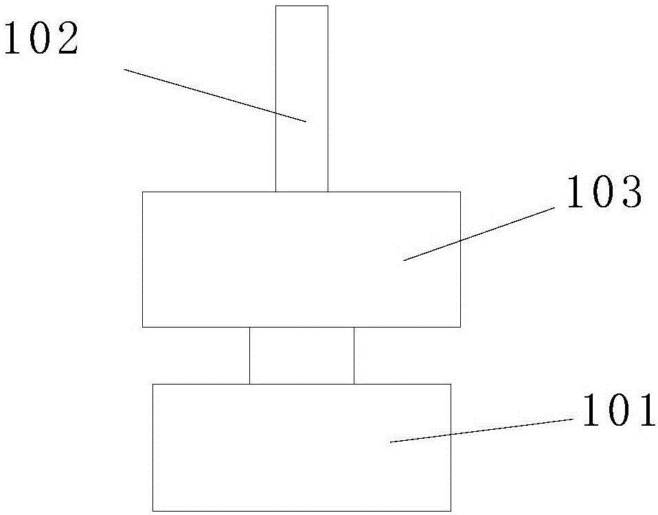
[0054] Figure 3a-3b These are two deformation structures based on Embodiment 1. A spring 102 is added to the pulse condition sensor shown in Embodiment 1, wherein the spring is a buffer assembly.

[0055] Spring 102 has two kinds of assembly methods: the first assembly method is as Figure 3a As shown, the two ends of the spring 102 are respectively screwed on the internal thread 204 at the top center of the flexible array sensor housing 203 and the external thread of the screw rod 206 to achieve elastic fixing of the flexible array sensor 200 and the elastic body 205 of the strain sensor. The second assembly method is as Figure 3b As shown, the screw 206 of the strain sensor elastic body 205 is screwed into the internal thread 204 provided on the top of the flexible array sensor housing 203 to realize the rigid fixation of the flexible array sensor 200 and the strain sensor elastic body 205; one end of the spring 102 It is screwed into the internal thread 212 of the strai...

Embodiment 3

[0059] This embodiment provides another way of implementing static force measurement in combination with strain gauge sensors and flexible array sensors: using existing industrial standard load cells or tension pressure sensors on the market for static force measurement, used to Replacing the strain sensor in Embodiment 1 and Embodiment 2 and combining it with the flexible array sensor in Embodiment 1 and Embodiment 2 can also achieve the effect of Embodiment 1, and the structural design is simpler.

[0060] Figure 4 The example in which the tension pressure sensor is an S-type tension pressure sensor 301 is given in , but those skilled in the art know that the strain gauge pressure sensor is not limited to this type, for example, it can also be a cantilever type, a spoke type, a plate ring type, Bellows type, bridge type, cylinder type and other styles.

[0061] There are threaded holes 302 on the top and bottom of the S-type tension pressure sensor 301 . The flexible arra...


PUM


Abstract

The invention discloses a pulse sensor capable of calibrating static force and a pulse collection device equipped with the pulse sensor. The pulse sensor capable of calibrating static force comprises a static force sensor, a dynamic force sensor and a buffer module, wherein the static force sensor is used for measuring pressure applied to a human to-be-detected part by the pulse sensor in the pulse-taking process; the dynamic force sensor is used for measuring dynamic force during pulse beating in the pulse-taking process; and the buffer module is connected with the dynamic force sensor and / or the static force sensor and is used for reducing interference of external jitter on pulse-taking measurement and preventing offset of the measuring position. According to the invention, the pulse information can be acquired in an all-around manner, and capabilities of performing high-sensitivity dynamic force detection, performing accurate static force measurement and acquiring three-dimensional haptical information are guaranteed.

Description

technical field [0001] The invention belongs to the technical field of medical instruments, and in particular relates to a pulse condition sensor and a pulse condition acquisition device capable of calibrating static force. Background technique [0002] Pulse diagnosis is an important technique in TCM diagnosis. The pulse method of traditional Chinese medicine has been passed down for thousands of years and has accumulated a lot of valuable experience. Some highly skilled Chinese medicine practitioners can accurately obtain information such as the patient's physique, the condition of the internal organs, and the degree of illness by virtue of the pulse-taking technique, so as to prescribe the right medicine. Modern medicine believes that blood flowing through the internal organs of the human body will inevitably carry a large amount of information about the internal environment of the human body. [0003] A pulse monitor is a device that can collect information on pressure...

Claims


Application Information

Patent Timeline
Patent Type & Authority Applications(China)
IPC IPC(8): A61B5/02
CPCA61B5/02A61B5/4854A61B5/6801A61B5/6825A61B5/683A61B5/6843A61B5/7203
Inventor 刘垚
Owner BEIJING BAIMAIZHILIAN TECH CO LTD
Why Eureka
Try Eureka