Perforating installing and positioning device and method for large member

A large component, installation and positioning technology, applied in the direction of transportation and packaging, load hanging components, etc., can solve the problems of inability to disassemble the positioning device, poor effect, etc., to achieve the effect of convenient installation and operation on site, ensuring construction safety, and light volume

Active Publication Date: 2016-11-16
SHANDONG UNIV
View PDF6 Cites 6 Cited by
  • Summary
  • Abstract
  • Description
  • Claims
  • Application Information

AI Technical Summary

Problems solved by technology

[0005] Theoretically speaking, the use of circular ring positioning devices can assist in the positioning of steel bars, but after actual use, it has been found that the effect of auxiliary positioning of circular rings in closed structures is poor, even if the positioning is successful (that is, the installation hole of the steel bar socket) In this case, the positioning device cannot be disassembled from the reinforcement

Method used


Image

  • Perforating installing and positioning device and method for large member
  • Perforating installing and positioning device and method for large member
  • Perforating installing and positioning device and method for large member

Examples


Embodiment 1

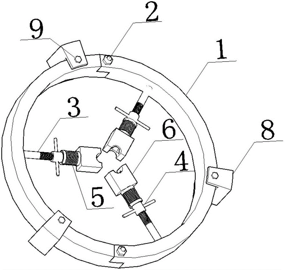
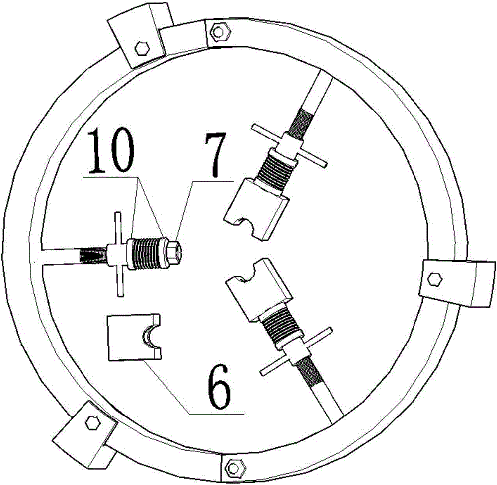
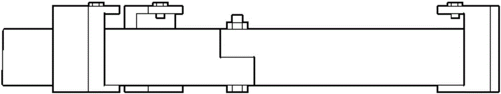
[0044] Embodiment 1: A positioning device for perforating and installing a large component, its structure is as follows Figure 1-7 shown, including:

[0045] The outer ring 1 of the detachable structure connected by bolts 2;

[0046] The inner side of the outer ring 1 is fixedly connected with one end of a guide rod 3;

[0047] A sleeve 4 and a nut 7 are installed on the guide rod 3 through a threaded pair, and the nut 7 is engaged in the alignment part 6. The alignment part 6 is preferably a horseshoe-shaped structure with a positioning groove in the middle;

[0048] An elastic component 5 is sleeved on the guide rod 3 , and the two ends of the elastic component 5 are pressed against the washer 10 . The outer washer 10 is pressed against the sleeve 4 and the inner washer 10 is pressed against the counter part 6 .

[0049] The alignment component 6 has a hexagonal hole and a flange 11, and the hole inside the flange 11 has an aperture greater than the diameter of the guide...

Embodiment 2

[0063] Embodiment 2: A positioning device for perforating a large component, including:

[0064] The outer ring 1 of the detachable structure connected by bolts 2;

[0065]The inner side of the outer ring 1 is fixedly connected with one end of a guide rod 3;

[0066] The guide rod 3 is a polished rod structure, and the rod body has a plurality of positioning holes perpendicular to the axis of the guide rod 3. The guide rod 3 is covered with a sleeve 4, and a positioning pin is inserted in one of the positioning holes to prevent the sleeve 4 from moving along the axis of the guide rod 3. The guide rod 3 moves in the direction of the outer ring 1.

[0067] Wherein, the front end of the guide rod is threaded, and a nut 7 is installed on the threaded part, and the nut 7 is engaged in the aligning part 6. The aligning part 6 is preferably a horseshoe-shaped structure with a positioning groove in the middle.

[0068] An elastic component 5 is sleeved on the guide rod 3 , and the t...


PUM


Abstract

The invention relates to a perforating installing and positioning device and method for a large member, and belongs to the relevant technical field of hoisting equipment. The device majorly comprises an outer ring of a detachable structure; the inner side of the outer ring is fixedly connected with guide rods; each guide rod is sleeved with an elastic part capable of moving along the guide rod; one end of each elastic part makes contact with an aligning part; the other end of each elastic part makes contact with a positioning sleeve installed on the corresponding guide rod; each aligning part is provided with an aligning groove used for containing a steel bar; and the aligning parts are matched to enable the axes of the steel bars to coincide with the axes of installing holes to complete installing and positioning of the member. According to the perforating installing and positioning device and method for the large member, accurate perforating installing of the member can be achieved by designing the brand-new structure.

Description

technical field [0001] The invention relates to the related technical field of hoisting equipment, in particular to a device and method for perforating and installing positioning of large components. Background technique [0002] Over the past few decades, with the continuous improvement of my country's engineering construction and assembly industry technology, and the realization of factory and prefabricated component production, more and more large components have been hoisted and assembled. Due to the increasing volume and weight of these assembly components, they are easily affected by many factors such as environmental wind force and hoisting equipment during hoisting, which makes hoisting accuracy difficult to guarantee. [0003] From the structural analysis of the component, the component mainly includes the component body and the steel bars protruding from the component body. When assembling, it is necessary to accurately insert the steel bars into the mounting hole...

Claims


Application Information

Patent Timeline
Patent Type & Authority Applications(China)
IPC IPC(8): B66C13/06B66C13/08
CPCB66C13/06B66C13/08
Inventor 王有志徐刚年安然尤伟杰袁泉张涛柳尚斌刘庆昌
Owner SHANDONG UNIV
Why Eureka
Try Eureka