
Efficient pipeline flocculating mixer and dosing and stirring device

A pipeline flocculation and mixer technology, applied in chemical instruments and methods, special treatment targets, water/sludge/sewage treatment, etc., can solve the problems of blade deformation and breakage, unstable operation, unevenness, etc., and reduce the sealing performance. requirements, stable and uniform stirring, easy and uniform stirring

Active Publication Date: 2016-11-16
吴云萍
View PDF4 Cites 5 Cited by
  • Summary
  • Abstract
  • Description
  • Claims
  • Application Information

AI Technical Summary

Problems solved by technology

[0004] 1. Due to the structure of the flocculation mixing tank itself, it is inevitable that when the agitator is stirring, the stirring force in the blind area will be insufficient or uneven, resulting in unsatisfactory and unstable flocculation effect
[0005] 2. The stirring speed of the agitator will not be too fast, resulting in uneven mixing of sludge and chemicals, and insufficient accumulated energy, resulting in many chemicals not being used most effectively
Increased the dosage of the agent, and the effect of flocculation is not ideal
[0006] 3. Because the mixing blades are too large and too long, it is easy to cause the deformation and breakage of the blades, resulting in unstable operation
The steel pipe used to transport sludge in the existing common pipeline mixer is a circular pipe structure. A through hole is opened from the side wall of the circular pipe, and the stirrer is inserted vertically for stirring. Since the stirring shaft of the stirrer is perpendicular to the central axis of the circular pipe, the stirring It is difficult for the mixing blade of the mixer to fit the arc-shaped tube wall, and the blind area is inevitable. The stirring force in the blind area is not enough or uneven, resulting in unsatisfactory and unstable flocculation effect.

Method used


Image

  • Efficient pipeline flocculating mixer and dosing and stirring device
  • Efficient pipeline flocculating mixer and dosing and stirring device
  • Efficient pipeline flocculating mixer and dosing and stirring device

Examples


Embodiment Construction

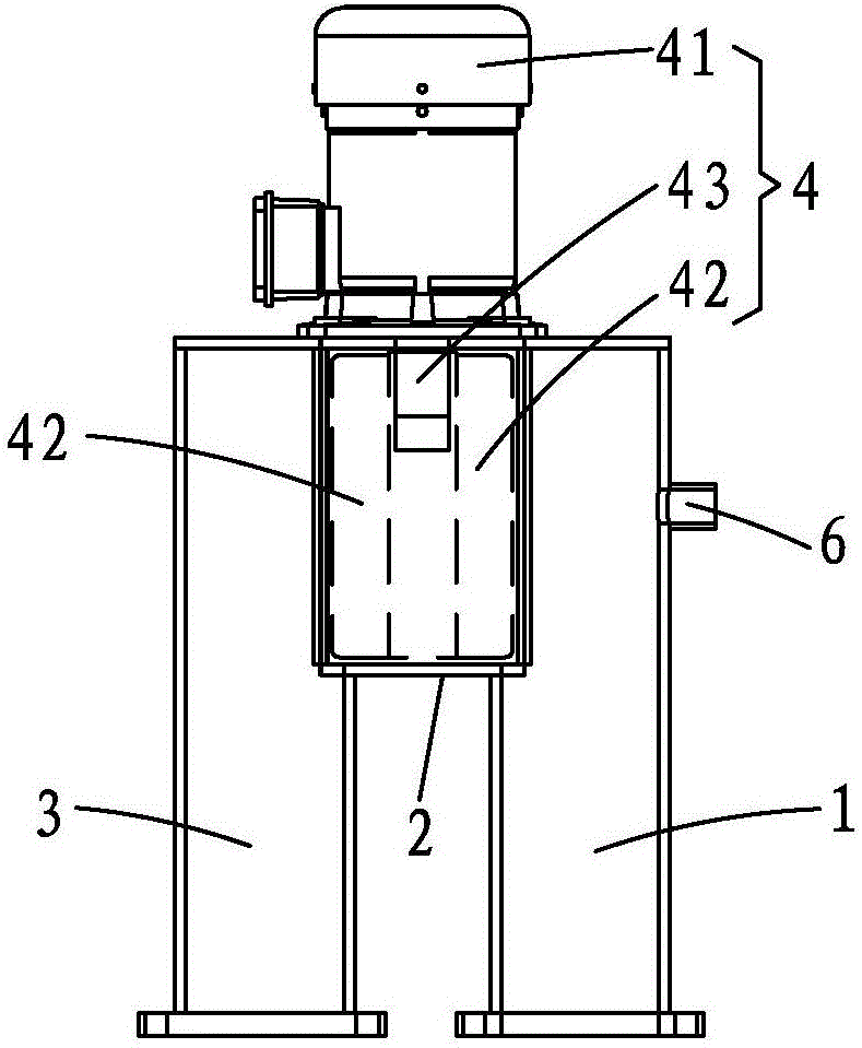
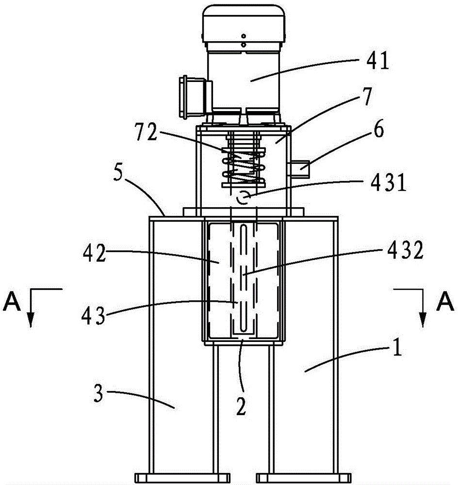
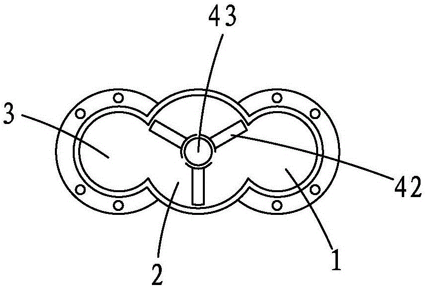
[0032] Such as Figure 1 to Figure 4 As shown, the high-efficiency pipeline flocculation mixer of the present invention includes a feed pipe 1, a stirring pipe 2, a discharge pipe 3 and an agitator 4, and the feed pipe 1, the stirring pipe 2, and the discharge pipe 3 are arranged in parallel and sequentially connected;

[0033] The stirring tube 2 is a round tube with blind ends at both ends, so that the stirring can be carried out in a relatively closed and narrow cavity, so that there is no blind area for stirring. The end of the feed pipe 1 opposite to the feed port is a blind end, and the end of the discharge pipe 2 opposite to the discharge port is a blind end. And the blind end of the feed pipe 1 and the blind end of the discharge pipe 3 are flush with a blind end of the stirring tube 2 , for example, they can be sealed by the same sealing plate 5 .

[0034] Such as image 3 and Figure 4 As shown, the side walls of the feed pipe 1 and the discharge pipe 3 are provid...


PUM


Abstract

The invention provides an efficient pipeline flocculating mixer which comprises a feed pipe, a stirring pipe, a discharge pipe and a stirrer, wherein the feed pipe, the stirring pipe and the discharge pipe are arranged in parallel and are communicated in sequence; the stirring pipe is a round pipe, and the two ends of the stirring pipe are blind ends; the stirrer comprises a driving motor, a stirring blade and a central shaft; one end of the central shaft is connected with the driving motor, and the other end of the central shaft is connected with the stirring blade; and the stirring blade is just contained in the stirring pipe. By solely arranging the stirring pipe in the shape of the round pipe, the axial length of the stirring blade meets the condition that the stirring blade is just contained in the stirring pipe, so that a dead zone can not occur, and the stirring is more sufficient.

Description

technical field [0001] The invention relates to a solid-liquid separation device, in particular to a pipeline flocculation mixer at the front end of the solid-liquid separation device. Background technique [0002] At the front end of the solid-liquid separation equipment, in order to ensure sufficient separation of mud and water, a flocculation mixing tank or some pipeline mixers will be added to the front end of the dehydrator. [0003] After the sludge at the bottom of the tank and the flocculant meet in the flocculation mixing tank, under the agitation of the agitator, the sludge and the flocculant are mixed and gradually form flocs. But this flocculation mixing tank has the following disadvantages: [0004] 1. Due to the structure of the flocculation mixing tank itself, it is inevitable that when the agitator is stirring, the stirring force in the blind area will be insufficient or uneven, resulting in unsatisfactory and unstable flocculation effect. [0005] 2. The s...

Claims


Application Information

Patent Timeline
IPC IPC(8): C02F11/14
CPCC02F11/14C02F2303/06
Inventor 吴云萍
Owner 吴云萍
Learn More