A thickener capable of handling high-concentration pulp

A concentrator and high-concentration technology, applied in the field of concentrators, can solve the problems of small pulp compression area, high concentrator height, and reduced equipment service life, so as to improve the mass concentration of underflow, reduce power consumption and wear, and promote secondary The effect of level settling

Active Publication Date: 2021-10-15
ANHUI ZHONG NENG MACHINERY MFG
View PDF23 Cites 0 Cited by
  • Summary
  • Abstract
  • Description
  • Claims
  • Application Information

AI Technical Summary

Problems solved by technology

[0005] The following problems still exist in the thickener in the prior art: 1) when the mass concentration of the underflow pulp reaches more than 45%-55%, the settlement of the ore particles will interfere with each other, and there will be a large mechanical resistance due to collision friction between each other, and the settling speed Therefore, the processing speed of high-concentration pulp is slow, and the power consumption and wear of the reaction chamber and rake plate will be increased, and the service life of the thickener will be reduced; 2) After the high-concentration concentrated pulp enters the discharge mechanism, it is easy to Condensation hangs on the inner wall to cause blockage, which will not only reduce the storage and discharge speed, but also increase the wear and tear of the equipment and reduce the service life of the equipment; 3) The overall height of the thickener is high, the stability is poor, and the pulp compression area is small, increasing 4) It is easy to block the flocculant adding pipe when the flocculant is added, and only one pipe is used to add the flocculant, so that the contact area between the flocculant and the pulp is small, and the flocculation is reduced. efficiency

Method used


Image

  • A thickener capable of handling high-concentration pulp
  • A thickener capable of handling high-concentration pulp
  • A thickener capable of handling high-concentration pulp

Examples


Embodiment Construction

[0038] The following will clearly and completely describe the technical solutions in the embodiments of the present invention with reference to the accompanying drawings in the embodiments of the present invention. Obviously, the described embodiments are only some, not all, embodiments of the present invention. Based on the embodiments of the present invention, all other embodiments obtained by persons of ordinary skill in the art without creative efforts fall within the protection scope of the present invention.

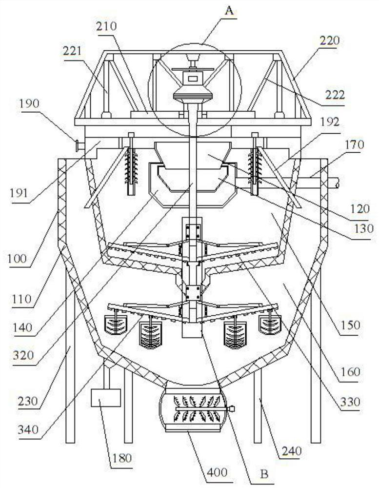
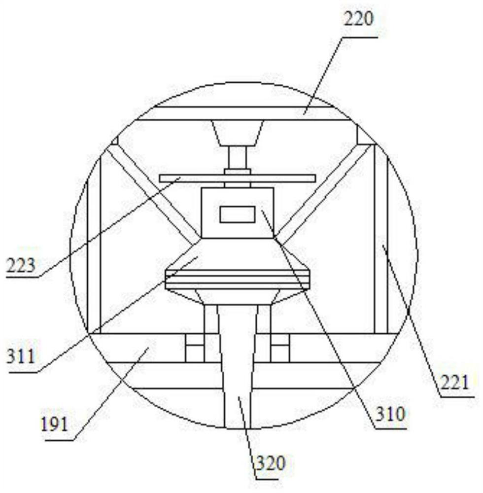
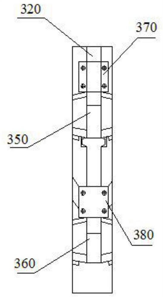
[0039] see Figure 1-7 As shown, this embodiment provides a concentrator capable of processing high-concentration pulp, including a reaction chamber 100 , an installation mechanism, a transmission mechanism, and a discharge mechanism 400 . Specifically, the installation mechanism is used for the installation and fixing of the reaction chamber 100 and the transmission mechanism, including a cover plate 210, a beam 220, a large support column 230, and a small support...


PUM


Abstract

The invention discloses a concentrator capable of processing high-concentration pulp, which includes a reaction chamber, an installation mechanism, a transmission mechanism, and a discharge mechanism. The reaction chamber includes a peripheral chamber, a drop pressure chamber, a primary processing chamber, and a secondary processing chamber , first-level settling chamber, and second-level settling chamber; during work, the slurry material enters the first-level treatment chamber along the feed pipe, and solids with larger particle sizes are deposited in the first-level treatment room and enter the first-level settling chamber through the screen. The rotation of the primary inclined main board accelerates the sedimentation and flocculation of the material, and the settled floc enters into the secondary settling chamber through the screen at the bottom of the primary settling chamber; in the secondary settling chamber, the secondary inclined main board drives the stirring shaft, stirring frame, Stirring blades are used for stirring, which promotes the secondary sedimentation of materials. The concentrator can process pulp with a mass concentration greater than 45%-55%, has a fast processing speed for high-concentration pulp, and has low power consumption and wear on the reaction chamber and rake plate, which improves the service life of the thickener.

Description

technical field [0001] The invention relates to the field of slurry processing equipment, in particular to a thickener capable of processing high-concentration pulp. Background technique [0002] Thickeners are widely used in mineral processing plants, and are mainly used in processes that require solid-liquid separation, such as leachate concentration and wastewater treatment. At present, thickeners are mainly divided into traditional thickeners, high-efficiency thickeners and high-efficiency deep cone thickeners. The working principle of the concentrator is that after the ore is mixed with the flocculant, it enters through the central vertical cylinder, and the outlet deflector guides the pulp from the feeding vertical cylinder to diffuse around, so that the pulp diffuses around and enters the pre-formed sediment layer , and the flocculant that comes in at the same time as the material forms a mud layer and settles to the bottom of the thickener; the liquid rises through t...

Claims


Application Information

Patent Timeline
Patent Type & Authority Patents(China)
IPC IPC(8): B01D21/02B01D21/01B01D21/20B01D21/22B01D21/24B01D21/28
CPCB01D21/01B01D21/02B01D21/20B01D21/22B01D21/2405B01D21/245B01D21/28B01D21/286
Inventor 杜友花
Owner ANHUI ZHONG NENG MACHINERY MFG
Why Eureka
Try Eureka