Manufacturing method of track iron backing plate structure in rail transit engineering

A technology of rail transit engineering and production method, which is applied in the field of production of rail iron backing plate structure, can solve the problems of low design value of sleeper top surface, sleeper error of track bed, etc. A wide range of effects

Active Publication Date: 2018-08-21
CHINA RAILWAY DESIGN GRP CO LTD
View PDF7 Cites 0 Cited by
  • Summary
  • Abstract
  • Description
  • Claims
  • Application Information

AI Technical Summary

Problems solved by technology

[0004] In view of the problems existing in the above-mentioned technologies, the object of the present invention is to provide a method for manufacturing a track iron backing plate structure in a rail transit project, so as to solve the problem of eliminating the error of the ballast sleeper caused by construction errors or structural heaves during operation
It can be used to solve the problem that the top surface of the sleeper is lower than the design value due to the construction error exceeding the limit or the structure sinking

Method used


Image

  • Manufacturing method of track iron backing plate structure in rail transit engineering
  • Manufacturing method of track iron backing plate structure in rail transit engineering
  • Manufacturing method of track iron backing plate structure in rail transit engineering

Examples


Embodiment Construction

[0019] The manufacturing method of the track iron backing plate structure in the track traffic engineering of the present invention is described in conjunction with the accompanying drawings.

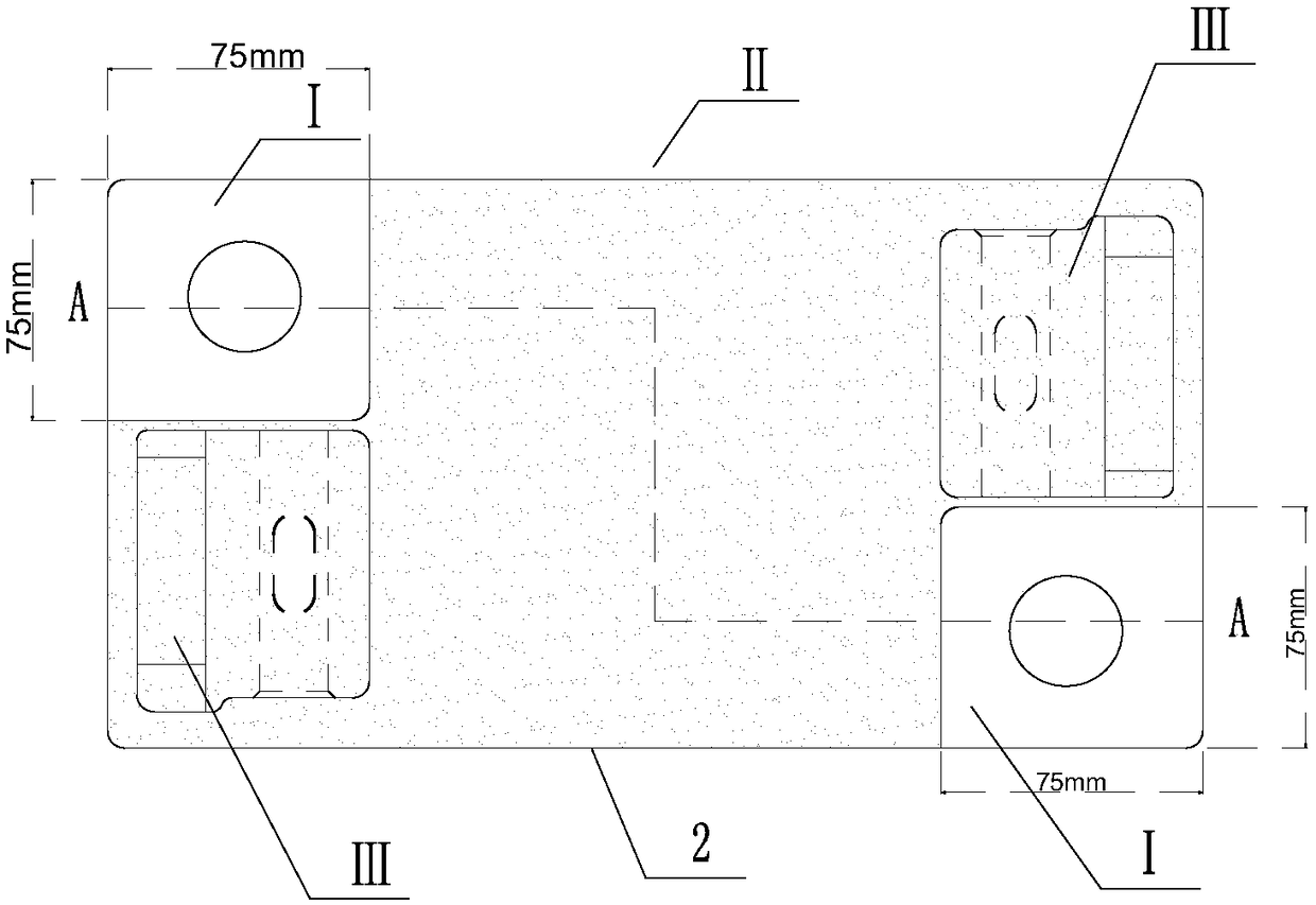
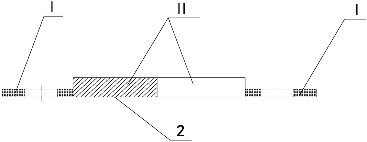
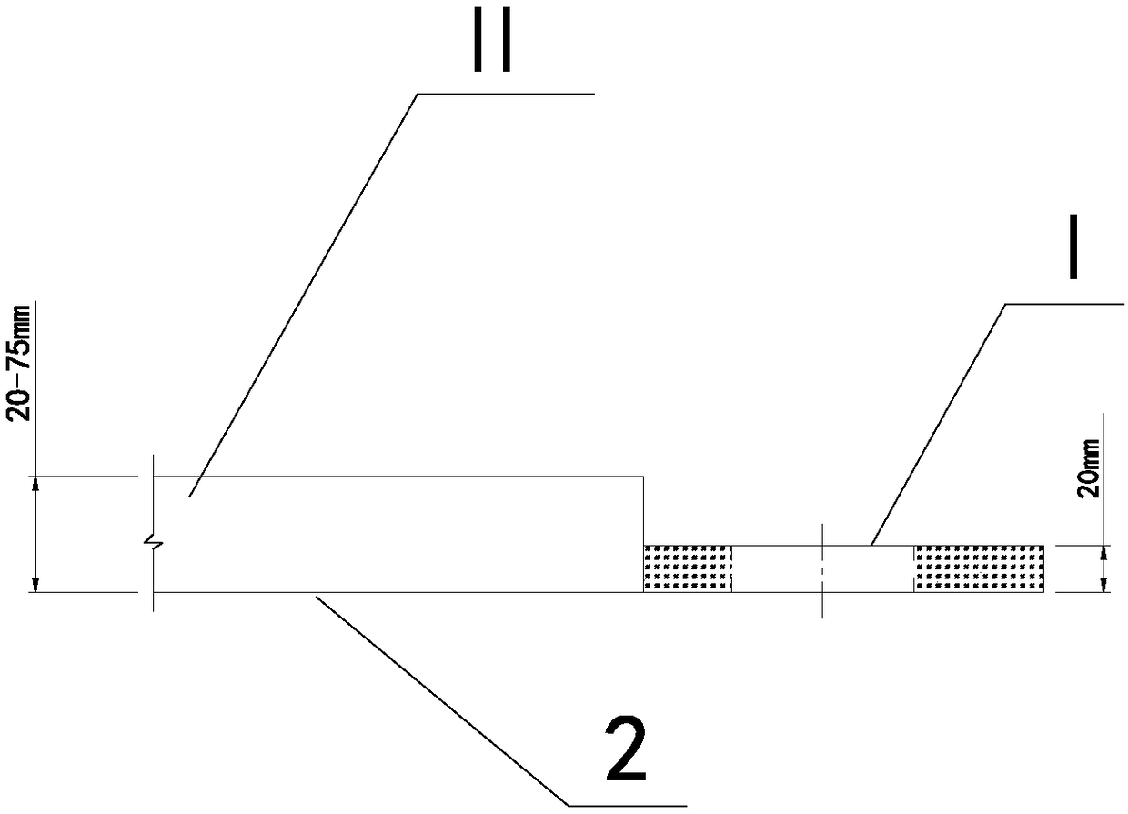
[0020] The design concept of the new iron backing plate structure of the rail transit engineering track of the present invention is based on: the original iron backing plate is also divided into three areas: the spike fixing area I, the supporting rail area II, and the spring strip fixing area III. The thickness is the same, generally 20mm, and can be appropriately reduced if necessary. The biggest difference between the structure of the iron backing plate and the original iron backing plate is that the thickness of the spike fixing area I remains unchanged. After the finite element analysis calculation and the actual project application test, the most reasonable 20mm is used, and it can be appropriately reduced if necessary. figure 2 As shown, the thickness values ​​of the supporting ...


PUM


Abstract

The invention provides an iron base plate structure for a rail in a rail transit project. An iron base plate adopting the structure is fixed on a sleeper below the steel rail by the aid of screw spikes; the iron base plate structure comprises spike fixing areas I, a steel rail supporting area II and elastic strip fixing areas III; the spike fixing areas I are located in two diagonal positions of the base plate surface of the iron base plate and are square, and the thickness of the iron base plate in the spike fixing areas I is 20 mm; the thickness of the steel rail supporting area II ranges from 20 mm to 75 mm; and the thickness of the elastic strip fixing areas III is consistent with the thickness of the steel rail supporting area II. The structure has the beneficial effect that the thickness of the steel rail supporting area II is adjustable with the adoption of the structure, so that sleeper height errors caused by construction errors or upheaval and settlement of a rail bed in the later period are made up and adjusted. Meanwhile, the thickness of the spike fixing areas I is unchanged, so that the firmness of bolts cannot be weakened due to thickening of the iron base plate. The problem of instability of the iron base plate due to lengthening of the bolts and the spikes due to overall thickening of the iron base plate is solved.

Description

technical field [0001] The invention relates to a manufacturing method of a rail iron backing plate structure in rail traffic engineering. Background technique [0002] Rail transit projects have been widely used in national railway passenger and freight transportation, urban passenger transportation and other fields, and have developed rapidly in recent years, especially urban rail transit projects, including subways, light rails, trams, etc. An effective solution to the problem of traffic congestion. [0003] In the process of construction and operation of rail transit projects, due to the complexity of comprehensive conditions, some errors in the track are inevitable. If the error exceeds the limit, it will affect the operation. It is necessary to regularly inspect the track and structure, and if the error exceeds the limit, it is necessary to take effective measures in time to eliminate the error and ensure the safety of operation. It is simple and economical to elimina...

Claims


Application Information

Patent Timeline
Patent Type & Authority Patents(China)
IPC IPC(8): E01B9/68
CPCE01B9/681E01B9/685
Inventor 马振海徐彩彩马艳雪黄弢李超袁斌王翔昊田苗盛张鸿逯璇王立存苗壮耿广晋
Owner CHINA RAILWAY DESIGN GRP CO LTD
Why Eureka
Try Eureka