
Method for controlling signal of scanning line of display

A signal control method and scanning line technology, applied in the field of signal control, can solve problems such as uneven pixel voltage, and achieve the effect of improving the color checkerboard phenomenon

Inactive Publication Date: 2013-04-17
CPT TECH GRP +1
View PDF0 Cites 0 Cited by
  • Summary
  • Abstract
  • Description
  • Claims
  • Application Information

AI Technical Summary

Problems solved by technology

[0011] In order to solve the above-mentioned uneven pixel voltage problem, the present invention provides a method for controlling the scan line signal of a display

Method used


Image

  • Method for controlling signal of scanning line of display
  • Method for controlling signal of scanning line of display
  • Method for controlling signal of scanning line of display

Examples


Embodiment Construction

[0037] The present invention will be described with preferred embodiments and aspects. Such descriptions are to explain the structure and procedures of the present invention, and are only used for illustration rather than to limit the patent scope of the present invention. Therefore, in addition to the preferred embodiment in the description, the present invention can also be widely implemented in other embodiments.

[0038] The invention provides a display scan line signal control method, which can be used in color sequential displays.

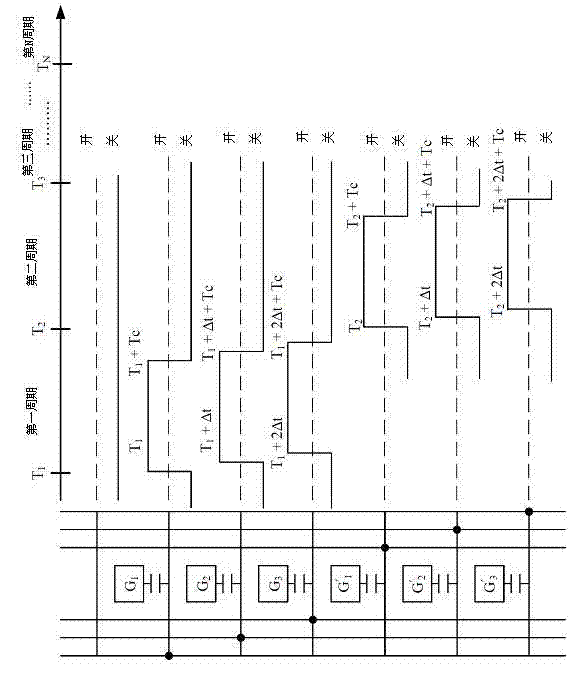
[0039] Such as figure 1 As shown, the present invention delays the scan line turn-on time and turn-off time of each pixel after the first pixel in each cycle of scan line control by a delay time (Δt) that increases in equal proportion to stagger each pixel The turn-on and turn-off time of the scan lines can be shortened, so that the uneven pixel voltage phenomenon caused by the simultaneous turn-on and turn-off of the scan lines of three pi...


PUM


Abstract

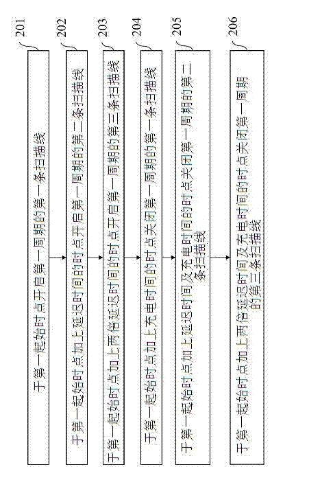
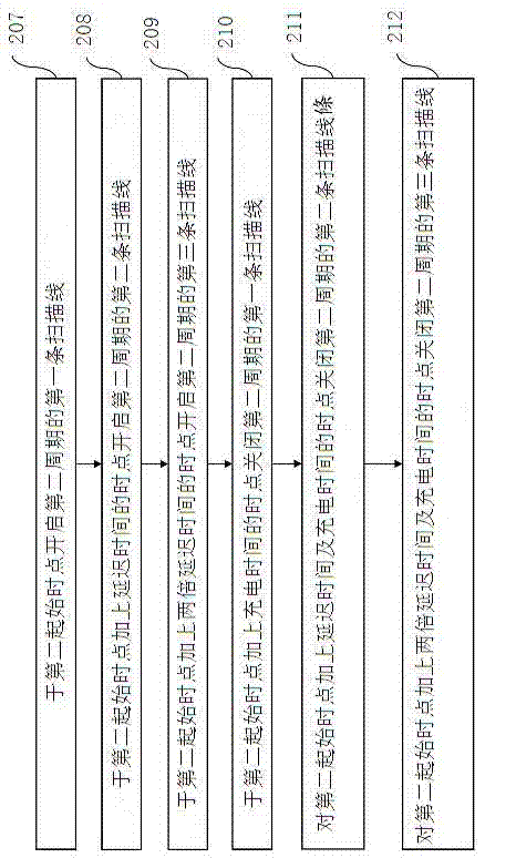
The invention provides a method for controlling a signal of a scanning line of a display. The method comprises the following steps: corresponding to a picture to be displayed, dividing the scanning time of a picture into N scanning periods according to the sequence in which the scanning lines are arranged, wherein the initial time point of each scanning period is T(N), N is a positive integer which is more than or equal to 1; and subsequently, at a time point T'(M) in the Nth scanning period, enabling an Mth scanning line within the Nth scanning period one by one in the sequence that the scanning lines are arranged, thus pixels corresponding to the scanning lines are charged, wherein M is a positive integer more than or equal to 1, the scanning time of the Mth scanning line comprises an enabling time point T'(M), delay time K*DetaT and charging time Tc, and K is equal to M-1, and the enabling time point of the Mth scanning line T'(M) is equal to T(N) + KDetaT. By applying the method provided by the invention, the situation that a colour checkerboard is produced in a display frame owning to the traditional signal control method can be effectively alleviated.

Description

technical field [0001] The present invention relates to signal control, in particular to a method for controlling a display scan line signal. Background technique [0002] In recent years, with the rapid development of imaging technology, liquid crystal displays (Liquid Crystal Displays; LCDs), which are thin in size, light in weight and have low electromagnetic radiation, have gradually become mainstream display products. [0003] A liquid crystal panel is composed of a plurality of pixels arranged in a matrix. By separately feeding the image data of each pixel to control the brightness of the pixel, so that the entire liquid crystal panel displays a picture. Since the pixels can only display the gray scale from light to dark, it is necessary to use other methods to display colors accordingly. [0004] A conventional liquid crystal display uses color filters to simultaneously display the three primary color components of a pixel, thereby displaying colors. One pixel of t...

Claims


Application Information

Patent Timeline
Patent Type & Authority Patents(China)
IPC IPC(8): G09G3/32G09G3/36
Inventor 杨登杰程一轩刘家麟戴文智陈光郎
Owner CPT TECH GRP
Learn More