Intelligent floor and construction method thereof

A construction method and intelligent technology, applied in the direction of floors, building components, buildings, etc., can solve the problems of poor mechanical performance of hollow floor slabs, and the inability of concrete bottom plates to participate in floor heating adjustment, and achieve convenient layout, simplified maintenance work, and simple operation. Effect

Inactive Publication Date: 2016-11-16
蒋朝晖
View PDF7 Cites 2 Cited by
  • Summary
  • Abstract
  • Description
  • Claims
  • Application Information

AI Technical Summary

Problems solved by technology

[0012] The purpose of the present invention is to provide an intelligent floor and its construction method, to solve the technical problem of poor overall mechanical performance of the existing hollow floor, and also to solve the technical problem that the concrete floor of the floor cannot participate in floor heating regulation

Method used


Image

  • Intelligent floor and construction method thereof
  • Intelligent floor and construction method thereof
  • Intelligent floor and construction method thereof

Examples


Embodiment 1

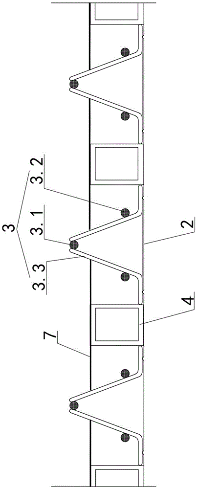
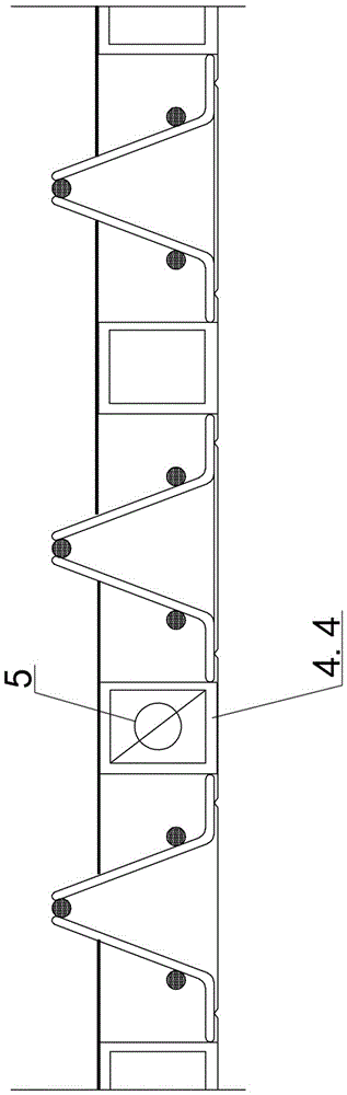
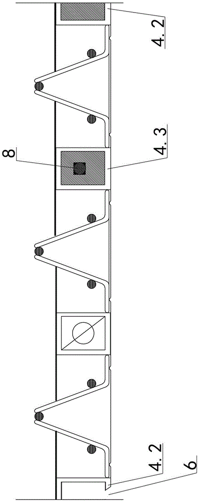
[0043] Embodiment one, see Figure 1-4 As shown, an intelligent floor slab includes a slab body, and the slab body includes a slab body concrete 1, a self-supporting profiled steel plate bottom form 2 at the bottom, embedded in the slab body concrete and fixed on the self-supporting profiled steel plate bottom A group of steel bar trusses 3 and a group of smart device tubes 4 on the upper side of the mold 2, the smart device tubes 4 are parallel to the steel bar trusses 3 along the longitudinal direction of the plate body, and are distributed between the steel bar trusses 3 at intervals along the transverse direction of the plate body. The smart device pipe 4 includes at least one hollow pipe through which the valve 5 in the pipe controls the ventilating and water-passing equipment outside the board, and the connection circuit in the pipe controls the induction device outside the board; those skilled in the art can implement the valve in any reliable manner. 5 Connection with ...

Embodiment 2

[0050] Embodiment two, see Figure 5 As shown, the difference from the first embodiment is that the smart device tubes 4 are all round tubes, and no ordinary hollow tube 4.1 is provided.

Embodiment 3

[0051] Embodiment three, see Image 6 As shown, the difference from the second embodiment is that all smart device tubes 4 are T-shaped tubes, and ordinary hollow tubes 4.1 are not provided.

[0052] The construction method of the intelligent floor slab of embodiment 1 includes the following construction steps:

[0053] Step 1: Process the self-supporting profiled steel plate base form 2, the steel bar truss 3 and the smart device tube 4 in the prefabricated component factory, design the type, shape and number of the smart device tube 4 according to the actual situation, and place them on the self-supporting profiled steel plate The bottom mold 2 is fixedly connected to the steel bar truss 3 and the intelligent device pipe 4, and the binding limit pressure piece 7 is fixed between the connected steel bar trusses 3 and on the upper side of the intelligent device pipe 4 to form a floor deck unit;

[0054] Step 2, the prefabricated floor deck unit is transported to the site, and...


PUM


Abstract

The invention discloses an intelligent floor and a construction method thereof. The intelligent floor comprises a floor body, the floor body comprises floor body concrete, a bottom self-bearing type profiled steel sheet bottom die, a set of steel bar trusses and a set of intelligent device pipes, wherein the steel bar trusses and the intelligent device pipes are embedded in the floor body concrete and fixed to the upper side of the self-bearing type profiled steel sheet bottom die; the intelligent device pipes are parallel to the steel bar trusses in the longitudinal direction of the floor body and are distributed between the steel bar trusses at an interval in the transverse direction of the panel body, and at least one intelligent device pipe controls a ventilation and water passing device outside the floor body through a valve located in the corresponding pipe and controls an induction device outside the floor body through a connecting circuit in the corresponding pipe. According to the intelligent floor, due to the adding of the intelligent device pipes, the use amount of the concrete is reduced, the self weight of the floor is reduced, the stress performance of the floor is improved, the control of the floor over the building temperature, humidity and ventilation is achieved, and arranging of pipelines of water, heating, electricity and the like is facilitated.

Description

technical field [0001] The invention belongs to the field of construction engineering, in particular to a floor slab and a construction method thereof. Background technique [0002] In recent years, with the development of construction technology, floor slabs have produced many forms as a separate load-bearing component, such as hollow-core slabs. Hollow floor slabs are generally provided with one or several total longitudinal channels to save materials and reduce weight. For example, the patent number is ZL01139994.5, and the Chinese patent titled "a kind of cast-in-place reinforced concrete hollow floor slab" discloses a kind of cast-in-place reinforced concrete hollow floor slab. The pot-shaped formwork composed of the surrounding side walls and the upper bottom plate is a cavity polyhedron structure connected with the lower bottom plate. The lower bottom plate of the formwork member is the structural bottom plate, and there are steel bars or prestressed steel bars, stee...

Claims


Application Information

Patent Timeline
IPC IPC(8): E04B5/48
CPCE04B5/48
Inventor 蒋朝晖
Owner 蒋朝晖
Why Eureka
Try Eureka