Combined coded lock

A coded lock and combined technology, applied in the field of coded locks, can solve the problems of anti-theft lock safety hazards, inconvenient practical application, inconvenient reversing, etc., and achieve the effects of improving safety, convenient reversing, and avoiding potential safety hazards

Active Publication Date: 2016-11-16
徐州宇之阳市场营销策划有限公司
View PDF4 Cites 7 Cited by
  • Summary
  • Abstract
  • Description
  • Claims
  • Application Information

AI Technical Summary

Problems solved by technology

[0002] At present, traditional anti-theft locks are mostly fingerprint combination locks combined with traditional mechanical emergency locks, or button-type mechanical combination locks combined with traditional mechanical emergency locks. When the unlocking method fails, the lock can only be unlocked by the key of the mechanical emergency lock, which is very inconvenient in practical application; and because the traditional mechanical emergency lock has a key hole, the anti-theft lock has a great potential safety hazard
In addition, although the existing anti-theft locks can also adapt to doors with different opening directions, it is very inconvenient to change the direction, requiring special tools, and the positions of the handle and the bolt need to be adjusted, which is not flexible enough

Method used


Image

  • Combined coded lock
  • Combined coded lock
  • Combined coded lock

Examples


Embodiment 1

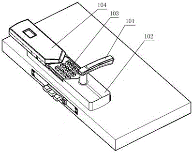
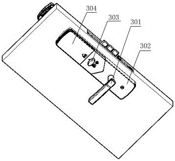
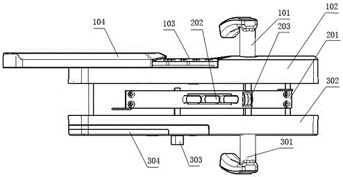
[0052] See figure 1 , figure 2 with image 3 , The embodiment of the present invention provides a combined combination lock, including an inner handle assembly, an outer handle assembly and a lock body, which further includes a clutch mechanism and a drive mechanism for driving the clutch mechanism provided on the outer handle assembly; the lock body includes a lock The housing 201, the lock tongue 202, and the linkage mechanism that drives the lock tongue 202 to move; the outer handle assembly can selectively drive the linkage mechanism through the clutch mechanism; the inner handle assembly is connected with the linkage mechanism and can directly drive the linkage mechanism. See Figure 15 , The inner lock knob is provided on the outer side wall of the inner handle assembly housing 302, and the inner lock limit rod connected with the inner lock knob passes through one end of the inner handle assembly housing 302 and is stuck in the inner lock fixing hole 212, and the lock ton...

Embodiment 2

[0070] Example 2 Handle reversing mechanism

[0071] See Figure 14 with Figure 15 , The second embodiment of the present invention provides an anti-theft lock handle reversing mechanism, including circular steering chuck (117 and 308) fixed on the handle, reset torsion spring C309, reversing plates (118 and 306) and Two arc-shaped steering slots are provided on the periphery of the steering plate (119 and 307) and the steering card (117 and 308). One end of the reversing plate (118 and 306) and the reversing plate (119 and 307) pass through the same screw Fixed, the other end of the reversing plate shrapnel (119 and 307) can pop up the reversing plate (118 and 306) without external force and make the reversing plate (118 and 306) stuck in the steering slot;

[0072] One end of the reversing plate (118 and 306) is fixed to the inner handle assembly housing 302 or the outer handle assembly housing 102.

[0073] One end of the reset torsion spring C309 is set on the outer handle ass...

Embodiment 3

[0076] Embodiment 3 Anti-theft lock clutch mechanism

[0077] See Image 6 , Figure 7 , Figure 8 with Picture 9 , The embodiment of the present invention provides a clutch mechanism for an anti-theft lock, including a clutch seat 107, the clutch seat 107 is sleeved with an outer shaft 108, the outer shaft 108 is provided with an unlocking square shaft 4, a clutch seat 107 and an outer shaft The corresponding positions of 108 are provided with hanging slots (115 and 116); the clutch seat 107 is restricted on the outer handle 101 by a clutch cover 121 with a through hole. The lock housing 201 is provided with a through hole 205 passing through the unlocking square shaft 4.

[0078] The clutch mechanism also includes a gear pin 110 that cooperates with the gear groove (115 and 116). The gear pin 110 is movably connected with the driving mechanism, and the driving mechanism can drive the gear pin 110 into the gear groove (115 and 116); After the stop pin 110 enters the stop groove ...


PUM


Abstract

The invention discloses a combined coded lock. The combined coded lock comprises an internal handle assembly, an external handle assembly and a lock body and further comprises an engagement-and-disengagement mechanism arranged on the external handle assembly and a drive mechanism for driving the engagement-and-disengagement mechanism. The lock body comprises a lock shell, lock tongues and a linkage mechanism for driving the lock tongues to move. The external handle assembly can selectively drive the linkage mechanism through the engagement-and-disengagement mechanism. The internal handle assembly is connected with the linkage mechanism and can directly drive the linkage mechanism. The combined coded lock has the beneficial effects that a fingerprint code lock body and a touch-tone mechanical coded lock body are combined to serve as a double-driver of the coded lock, the potential safety hazards brought by a traditional mechanical lock are avoided, and the safety of the coded lock is improved. Furthermore, the combined coded lock is further provided with a handle reversing gear, and mounting is flexible; and the linkage mechanism is in cooperation with the double-drive mechanism and the engagement-and-disengagement mechanism to form a complete structure, and the demands of people on the high safety of anti-theft locks, convenient and fast use, flexible mounting and the like can be well met.

Description

Technical field [0001] The present invention relates to the technical field of code locks, in particular to a combined code lock combining a push-button mechanical code and a fingerprint code. Background technique [0002] At present, the traditional anti-theft locks are mostly fingerprint code locks combined with traditional mechanical emergency locks, or push-button mechanical code locks combined with traditional mechanical emergency locks. Due to the use of a quick unlocking method, such as fingerprint password unlocking or push-button mechanical password unlocking, when fast When the unlocking method fails, the key of the mechanical emergency lock can only be used to unlock the lock, which is very inconvenient in practical application; and because the traditional mechanical emergency lock has a key socket, the anti-theft lock has a great security risk. In addition, although the existing anti-theft lock can also adapt to doors with different opening directions, it is very inco...

Claims


Application Information

Patent Timeline
IPC IPC(8): E05B63/04E05B55/06E05B15/10E05B17/20E05B49/00
CPCE05B15/108E05B17/2007E05B49/00E05B55/06E05B63/04
Inventor 刘振林周建永
Owner 徐州宇之阳市场营销策划有限公司
Why Eureka
Try Eureka