Supercharge Your Innovation With Domain-Expert AI Agents!

Gas drilling and coring tool

A gas drilling and coring technology, which is applied in the direction of extracting undisturbed core devices, earthwork drilling and mining, etc., can solve the problems of low average yield of cores, core jamming, core grinding, adverse effects of geological exploration, etc., and achieve the goal of increasing the average yield Effect

Inactive Publication Date: 2016-11-16
CCDC PETROLEUM CORING TECH
View PDF7 Cites 2 Cited by
  • Summary
  • Abstract
  • Description
  • Claims
  • Application Information

AI Technical Summary

Problems solved by technology

[0002] In the case of gas drilling, the coring operation is carried out. Due to the negative pressure in the well, the stratum exposed at the bottom of the well bears huge in-situ stress. The cracks develop and release the pressure to form a thin sheet core. In addition, the high-speed flow of pressurized gas in the annulus of the inner and outer cylinders of the coring tool and the throat of the core bit scours the core, causing the coring tool to generate a swinging force, which is easy to At the same time, the thin flaky core column will lean against the inner wall of the inner cylinder and there is not enough weight to apply and maintain sufficient pressure on the core claws, which will loosen the core claws and cause core loss. Using conventional coring tools for gas drilling and coring operations has an extremely low average core recovery rate, which has a negative impact on geological exploration

Method used


Image

  • Gas drilling and coring tool
  • Gas drilling and coring tool
  • Gas drilling and coring tool

Examples


Embodiment Construction

[0017] In order to make the objects and advantages of the present invention clearer, the present invention will be further described in detail below in conjunction with the examples. It should be understood that the specific embodiments described here are only used to explain the present invention, not to limit the present invention.

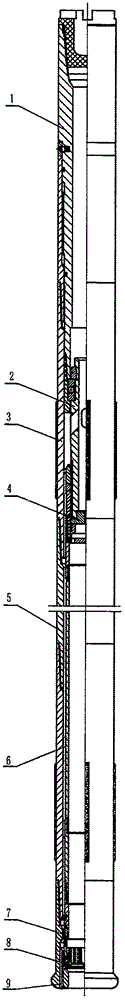
[0018] like figure 1 As shown, the embodiment of the present invention provides a gas drilling coring tool, including a safety joint 1, a rotating assembly 2, a difference nipple 3, a gas splitter joint 4, a coring outer cylinder 5, a coring inner cylinder 6, The core claw assembly 7, the drill bit throat sealing device 8 and the gas coring bit 9, the middle part of the safety joint 1 is threaded with the difference nipple 3, and the lower part is threaded with the rotating assembly 2; the lower part of the rotating assembly 2 It is threadedly connected with the gas distribution joint 4; the lower part of the gas distribution joint 4 is threade...


PUM


Abstract

The invention discloses a gas drilling and coring tool which comprises a safe connector, a rotation assembly, a difference short section, a gas dividing connector, an outer coring cylinder, an inner coring cylinder, a core catcher composite member, a drill bit throat sealing device and a gas coring drill bit. The middle portion of the safe connector is in threaded connection with the difference short section, and the lower portion of the safe connector is in threaded connection with the rotation assembly. The lower portion of the rotation assembly is in threaded connection with the gas dividing connector. The lower portion of the gas dividing connector is in threaded connection with the inner coring cylinder. The lower portion of the inner coring cylinder is in threaded connection with the core catcher composite member. The lower portion of the difference short section is in threaded connection with the outer coring cylinder. The lower portion of the outer coring cylinder is in threaded connection with the gas coring drill bit. The drill bit throat sealing device is arranged between the gas coring drill bit and the core catcher composite member. By the adoption of the gas drilling and coring tool, the situations that high-pressure gas makes direct contact with the core, washout is caused to the core, and accordingly the success rate of coring operation is affected are avoided; and the average core yield rate of gas drilling and coring operation is increased.

Description

technical field [0001] The invention relates to the field of gas drilling, in particular to a gas drilling coring tool. Background technique [0002] In the case of gas drilling, the coring operation is carried out. Due to the negative pressure in the well, the stratum exposed at the bottom of the well bears huge in-situ stress. The cracks develop and release the pressure to form a thin sheet core. In addition, the high-speed flow of pressurized gas in the annulus of the inner and outer cylinders of the coring tool and the throat of the core bit scours the core, causing the coring tool to generate a swinging force, which is easy to At the same time, the thin flaky core column will lean against the inner wall of the inner cylinder and there is not enough weight to apply and maintain sufficient pressure on the core claws, which will loosen the core claws and cause core loss. The average core recovery rate of gas drilling and coring operations using conventional coring tools i...

Claims


Application Information

Patent Timeline
Patent Type & Authority Applications(China)
IPC IPC(8): E21B25/00
CPCE21B25/00
Inventor 李伟成陈晓彬陈立刘彬胡畔何超陈文才
Owner CCDC PETROLEUM CORING TECH
Features
  • R&D
  • Intellectual Property
  • Life Sciences
  • Materials
  • Tech Scout
  • Unparalleled Data Quality
  • Higher Quality Content
  • 60% Fewer Hallucinations
Learn More