Ultraviolet LED helicopter rotor lamp

A technology for helicopter rotors and helicopters, applied in the field of LED lighting, can solve the problems of cumbersome maintenance in the later stage, the installation method is not firm, and the reliability is reduced, so as to overcome the problems of line damage and fracture, adapt to the airborne environment requirements, and improve the installation reliability. Effect

Inactive Publication Date: 2016-11-16
Anhui Huaxia Photoelectrics Co Ltd
View PDF6 Cites 2 Cited by
  • Summary
  • Abstract
  • Description
  • Claims
  • Application Information

AI Technical Summary

Problems solved by technology

[0002] The rotor light is an indispensable light source for indicating the outer contour of every helicopter. During the flight of the helicopter, a closed halo is formed on the propeller blade to serve as a warning. However, the installation method of the light source has always been a technical problem. The specific reasons are as follows : A. The installation method is not firm: when the helicopter is working, the propeller is in a high-speed rotation state, and the huge centrifugal force will cause the light source installed on the blade to break away from the body and be thrown out, causing danger and injury
B. Line loss: Since the propeller is in a rotating state when the helicopter is working, the lead-out line will also rotate with the light source on the propeller, so it will cause damage to the lead-out line and even break it, making it difficult to realize the function
C. Poor structural safety and reliability: If the light source is installed on the propeller, during the flight of the helicopter, the light source that rotates with the propeller blades is easily damaged under high-speed rotation, which reduces its reliability and affects its life
[0003] To sum up, the lighting method of installing the light source on the propeller blade of the helicopter not only wastes precious onboard energy, but also the installation method is not firm, the life is short, the later maintenance is cumbersome, and the structural safety and reliability are not high

Method used


Image

  • Ultraviolet LED helicopter rotor lamp
  • Ultraviolet LED helicopter rotor lamp
  • Ultraviolet LED helicopter rotor lamp

Examples


Embodiment Construction

[0021] Referring to the accompanying drawings, through the description of the embodiments, the specific implementation of the present invention, such as the shape, structure, mutual position and connection relationship between the various parts, the function and working principle of each part, and the manufacturing process And the method of operation and use, etc., are described in further detail to help those skilled in the art have a more complete, accurate and in-depth understanding of the inventive concept and technical solutions of the present invention.

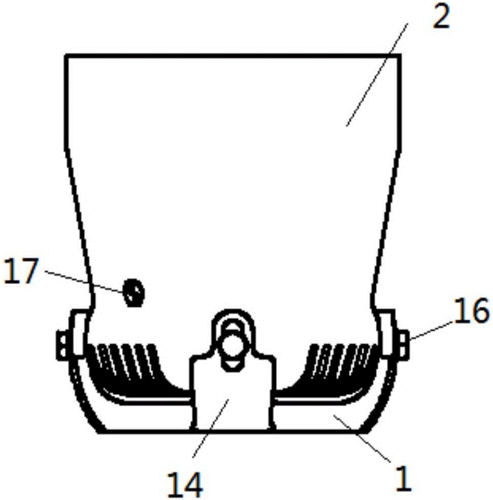
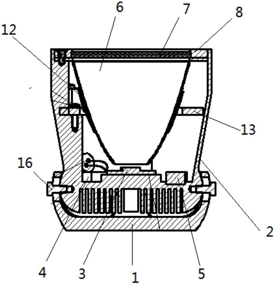
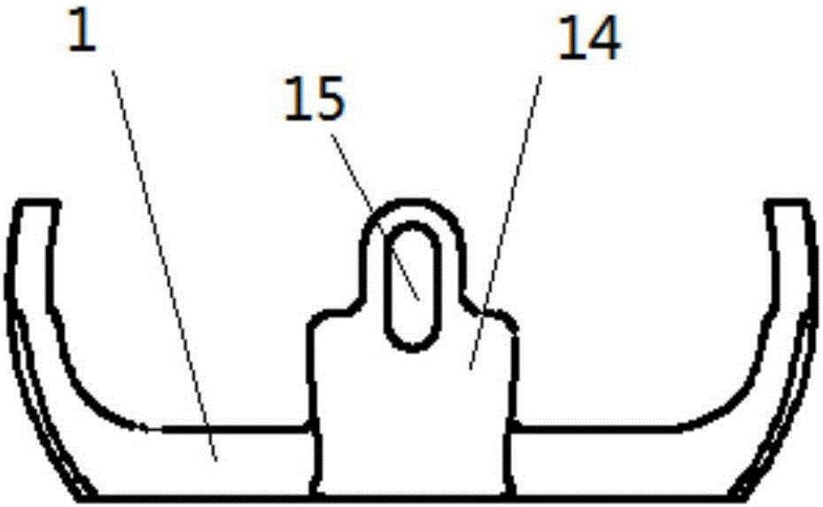
[0022] The main body of the ultraviolet LED helicopter rotor lamp of the present invention is a lamp body, which needs to cooperate with the helicopter rotor blades with a fluorescent coating to form a light emitting system to work. During specific installation, the lamp body is fixedly installed on the helicopter fuselage at the lower position of the helicopter rotor blades. When working, the lamp body emits ultraviolet...


PUM


Abstract

The invention discloses an ultraviolet LED helicopter rotor lamp, the lamp body comprises a fixed support and a main body shell capable of swinging relative to the fixed support, an ultraviolet LED module, a driving module and a filtering module are arranged at the bottom of the inner cavity of the main body shell, a reflection cup with a parabolic curved surface is arranged above the ultraviolet LED module, a glass sheet is arranged at the top end of the reflection cup, and a front cover fixed to the top end of the main body shell is arranged on the glass sheet. By use of the LED, the service life of the product can reach thousands of hours, so that the later maintenance cost is greatly reduced; green visible light is emitted in a manner of exciting the fluorescent coating through the ultraviolet rays, the warning effect is good, and the principle is ingenious; the lamp body can be fixed on the helicopter body, so that the problems of line loss and breakage are completely overcome, and the requirement on the airborne environment is better met, the mounting reliability is greatly improved; the light-emitting angle of the lamp body is adjustable, so that the optimal warning effect is ensured.

Description

technical field [0001] The invention belongs to the field of LED lighting, and in particular relates to an ultraviolet LED light source product that provides contour indication for helicopter rotors at night. Background technique [0002] The rotor light is an indispensable light source for indicating the outer contour of every helicopter. During the flight of the helicopter, a closed halo is formed on the propeller blade to serve as a warning. However, the installation method of the light source has always been a technical problem. The specific reasons are as follows : A, the installation method is not firm: when the helicopter is working, the propeller is in a high-speed rotation state, and the huge centrifugal force will cause the light source installed on the blade to break away from the body and be thrown out, thereby causing danger and injury. B. Line loss: Since the propeller is in a rotating state when the helicopter is working, the lead-out line will also rotate wit...

Claims


Application Information

Patent Timeline
Patent Type & Authority Applications(China)
IPC IPC(8): F21S8/00B64D47/06F21V7/00F21V21/00F21Y115/10F21W111/00
CPCF21S8/00B64D47/06F21V7/00F21V21/00F21W2111/00
Inventor 胡海城沈岳毕竞罗菲刘娟
Owner Anhui Huaxia Photoelectrics Co Ltd
Why Eureka
Try Eureka