Eureka AIR delivers breakthrough ideas for toughest innovation challenges, trusted by R&D personnel around the world.

Safety casting production system for refractory material

A refractory material and production system technology, applied in the direction of ceramic molding machines, manufacturing tools, furnace cooling devices, etc., can solve the problems of damaged walls, low pouring efficiency, and diffuse steam in the factory area, so as to improve service life, prevent steam pollution, The effect of improving productivity

Active Publication Date: 2016-11-16
郑州东方安彩耐火材料有限公司
View PDF6 Cites 0 Cited by
  • Summary
  • Abstract
  • Description
  • Claims
  • Application Information

AI Technical Summary

Problems solved by technology

The disadvantages of this cooling structure are: the temperature of the cooling water is high after being heated by the electric arc furnace, and even boiling occurs when the flow rate is small; when the cooling water is discharged, the steam diffuses, which pollutes the factory area and damages the walls of the factory area due to long-term humidity
At present, domestic manufacturers of molten casting refractories basically adopt the method of driving or forklift lifting to cast. The biggest disadvantage of this pouring method is that the driving and forklift have to have a running process after each pouring. It belongs to intermittent production. According to different brick shapes There may even be more than six cases of pouring in each furnace, making the pouring time about 30 minutes, which results in a very low pouring efficiency. During this period, the electric furnace has to keep heating the material liquid in the electric arc furnace, resulting in increased power consumption

Method used


Image

  • Safety casting production system for refractory material
  • Safety casting production system for refractory material
  • Safety casting production system for refractory material

Examples


Embodiment Construction

[0047] figure 1 The direction indicated by the middle arrow is the flow direction of the fluid.

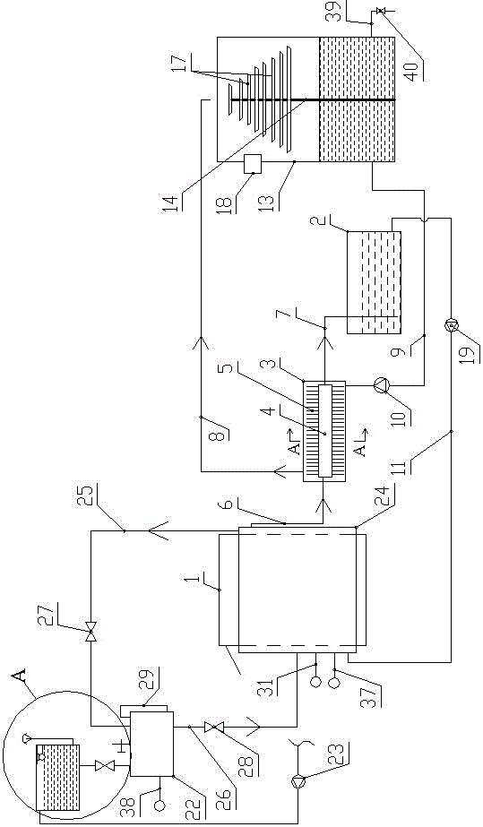
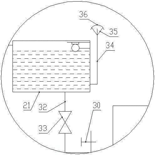
[0048] Such as Figure 1 to Figure 8 As shown, the refractory safe pouring production system of the present invention includes an electric arc furnace 1, a heat exchanger, a water storage tank 2, a cooling tower, an elevated water tank 21, a closed replenishment water tank 22, a replenishment pump 23 and a refractory rotary pouring device 91;

[0049] The refractory material rotary pouring device 91 includes a pouring base 43, a pouring support plate 44 and a pouring rotary bearing plate 45, and the horizontal sections of the pouring support plate 44 and the pouring rotary loading plate 45 are regular hexagons of the same size;

[0050] The pouring base 43 is fixedly connected with a pouring support column 46, a pouring stepper motor 47 and a pouring reducer 48 connected with the pouring stepper motor 47,

[0051] Two pouring support columns 46 are respectively provided at the l...


PUM


Abstract

The invention discloses a safety casting production system for a refractory material. The safety casting production system comprises an electric arc furnace, a heat exchanger, a water storage tank, a cooling tower, a head water tank, a water supplementing tank arranged in a sealed manner, a water supplementing pump and a refractory material rotating casting device. The refractory material rotating casting device comprises a casting base, a casting supporting plate and a casting rotating bearing plate. A water jacket is arranged on the electric arc furnace and is connected with the water supplementing tank. The water supplementing tank is connected with the head water tank, and the head water tank is connected with the water supplementing pump. According to the safety casting production system, the phenomenon that the electric arc furnace releases high-temperature thermal pollution to the outside can be avoided, the phenomenon that steam is dispersed into a plant in the production process is avoided, the phenomenon that cooling water releases steam pollution outwards is avoided, in addition, water resources can be recycled, the electric arc furnace is effectively cooled, rotating casting is achieved in the production process, the time needed for replacing casting boxes is greatly shortened, and the production efficiency is improved. According to the safety casting production system, the work safety of the electric arc furnace can also be ensured during the accidental power failure.

Description

technical field [0001] The invention relates to the technical field of refractory material production, in particular to a refractory pouring system. Background technique [0002] In the production process of molten casting refractories, electric arc furnace is commonly used equipment. During operation, the electric arc furnace melts the refractory raw materials in it, so it needs to maintain a high temperature continuously during the production process. Excessively high temperatures can reduce equipment life and prevent workers from working properly in the workshop. Therefore, it is necessary to cool the furnace wall of the electric arc furnace. While maintaining the high temperature in the furnace, control the high temperature area in the electric arc furnace to prevent a large amount of heat from being transferred to the environment, reduce the service life of the equipment, and make the workshop unsuitable for manual work. Operation. [0003] The existing cooling struc...

Claims


Application Information

Patent Timeline
Patent Type & Authority Applications(China)
IPC IPC(8): F27D1/12B28B1/14
CPCB28B1/14F27D1/12
Inventor 魏晓敏赵新成谢建雄王小东
Owner 郑州东方安彩耐火材料有限公司
Why Eureka
Eureka Blog
Learn More