Exposed Fuze Transport Vibration Test Fixture

A vibration test and fuze technology, applied in the field of fuzes, can solve the problems of easy resonance, low test efficiency, and non-compliance with the rigid connection between the fixture and the vibration table, to avoid resonance and avoid top-heavy effects.

Inactive Publication Date: 2018-09-18
国营第八四四厂
View PDF13 Cites 0 Cited by
  • Summary
  • Abstract
  • Description
  • Claims
  • Application Information

AI Technical Summary

Problems solved by technology

[0004] 1 Due to the unreasonable material selection and structural design of the traditional test fixture, resonance is easy to occur during the vibration test
Resonance will cause great deformation and dynamic stress in the mechanical and structural parts of the test piece, and even cause damage to the internal structure, thus losing its main function
[0005] 2. The traditional test fixture has only 21 clamping stations, which cannot meet the requirement of 26 rounds of commonly used test samples at one time. It needs to be divided into two times to realize the test of the full sample size. The test efficiency is low and the test cost increases.
[0006] 3. Due to the size of the connection hole, the traditional test fixture and the vibrating table cannot be fixed directly, and a conversion plate is needed in the middle to realize the connection and fixation. This method does not meet the requirements for a complete rigid connection between the fixture and the vibrating table, and the vibration transmitted to the test piece and energy are distorted, and the installation of the fixture before the test takes a long time

Method used


Image

  • Exposed Fuze Transport Vibration Test Fixture
  • Exposed Fuze Transport Vibration Test Fixture
  • Exposed Fuze Transport Vibration Test Fixture

Examples


Embodiment Construction

[0027] The present invention will be described in further detail below in conjunction with the accompanying drawings.

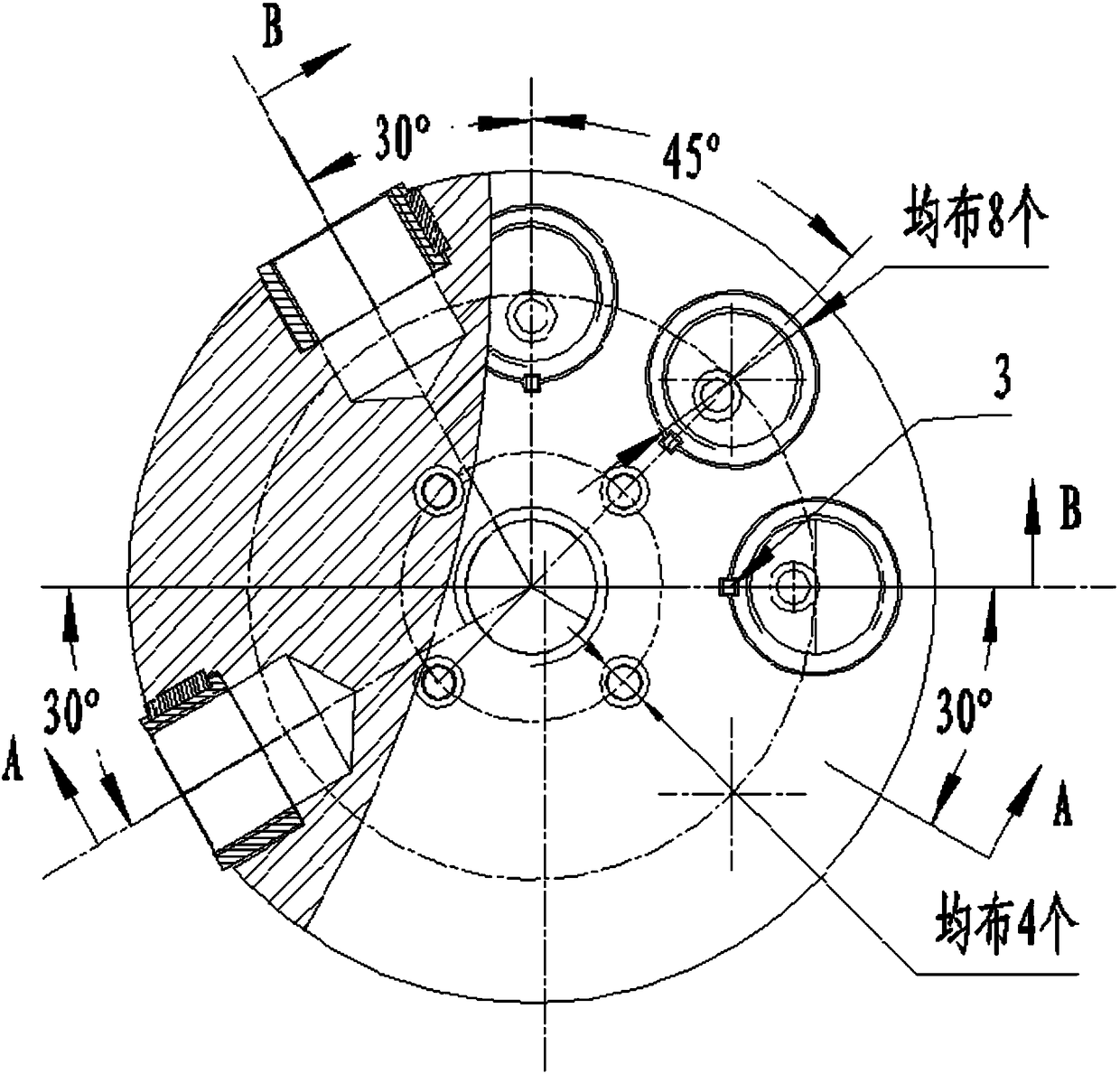
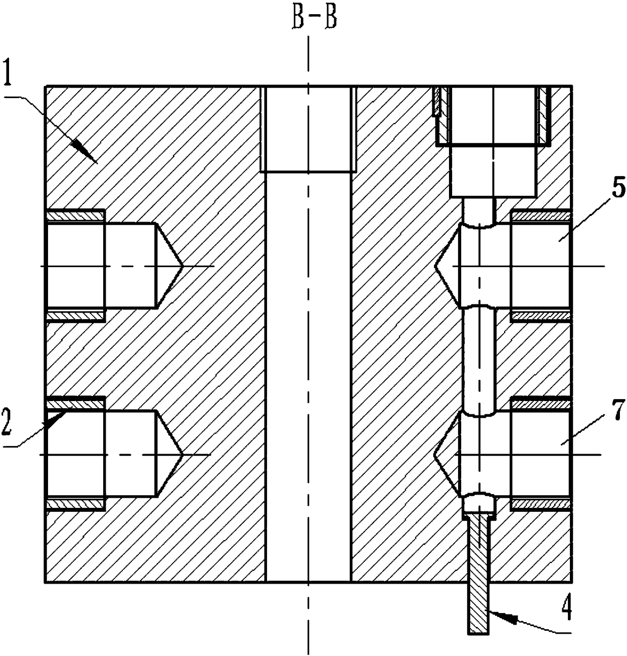
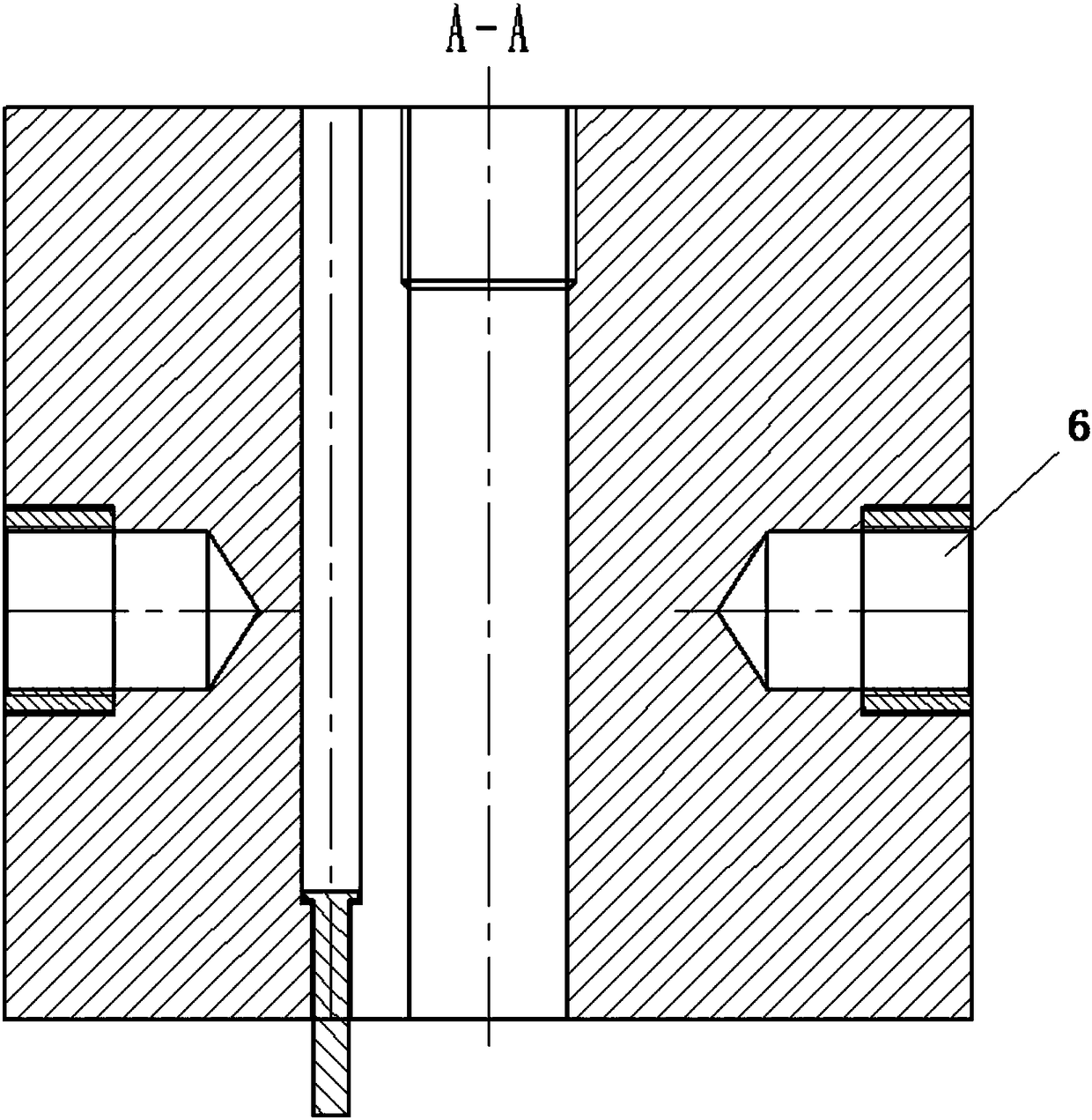
[0028] Such as Figure 1.1 As shown, a bare fuze transport vibration test fixture of the present invention includes: 1 body 1, 26 screw sleeves 2, 26 pin keys 3, and 12 connecting rods 4.

[0029] The body 1 is a cylinder with 27 fuze installation holes in total, one of which is the center hole of the cylinder, called the central installation hole, which is a through hole and has internal threads; the remaining 26 installation holes are light holes , The inner walls of the 26 mounting holes all leave a square groove compatible with the pin key 3, and the direction is arbitrary.

[0030] The upper ports of 9 of the 27 mounting holes are located on the upper end surface of the cylinder, including 1 central mounting hole and 8 vertical mounting holes. The axes of these 9 mounting holes are parallel to the central axis of the body 1 . The central mounting hole i...


PUM


Abstract

The invention discloses an exposed fuse transport vibration test fixture, which belongs to the technical field of fuses. The exposed fuse transport vibration test fixture can avoid the occurrence of resonance during the fuse testing process, and comprises a body 1, 26 thread sleeves, 26 pin keys and connecting rods. The exposed fuse transport vibration test fixture adopts integral forming, adopts a cylindrical structural pattern in shape, improves the first-order resonance frequency, avoids the occurrence of resonance during the testing process, adopts rigid connection, ensures that the vibration and energy of a vibration stand are transferred to a tested sample in a distortionless manner, is convenient in installation and operation, and improves test efficiency.

Description

technical field [0001] The invention belongs to the technical field of fuzes, and relates to a transportation vibration test jig, which can be used for exposed fuze products in transportation vibration tests. Background technique [0002] The design of the test fixture is a technology, and the main reference books in the design include "Environmental Test Technology Training Textbook", "Fuze Environment and Performance Test Method" and other materials. [0003] It is well known in the industry that the test acceptance process of fuze products requires transportation vibration test, and the design and use of vibration fixture is an important link in the vibration test process. The test fixture is the transition body connecting the test piece and the vibrating table surface, mainly to transmit the vibration and energy of the vibrating table to the test piece without distortion. Traditional test fixtures mainly have the following disadvantages: [0004] 1 Due to the unreasona...

Claims


Application Information

Patent Timeline
Patent Type & Authority Patents(China)
IPC IPC(8): G01M7/02
CPCG01M7/027
Inventor 甘延湖王涛韩景潘瀚杜文辉崔纯智
Owner 国营第八四四厂
Why Eureka
Try Eureka