Electrodynamic vibration shaker
An electro-dynamic vibration table and moving coil technology, applied in vibration testing, measuring devices, testing of machine/structural components, etc., can solve the problem of reducing the mechanical strength and stiffness of the metal bobbin 4, affecting the first-order resonance frequency of the moving coil 7, It is not conducive to the heat dissipation of the moving coil 7, and achieves the effect of improving the practicability, flexible implementation and compact structure
- Summary
- Abstract
- Description
- Claims
- Application Information
AI Technical Summary
Problems solved by technology
Method used
Image
Examples
Embodiment 1
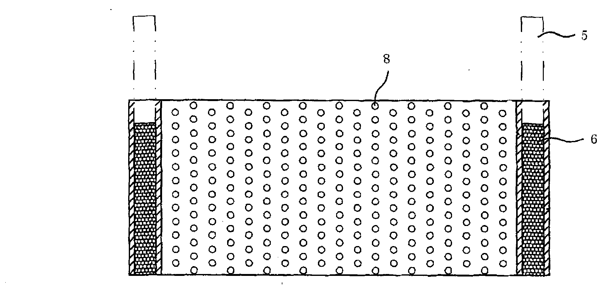
[0025] Embodiment one: see attached figure 2 as shown,
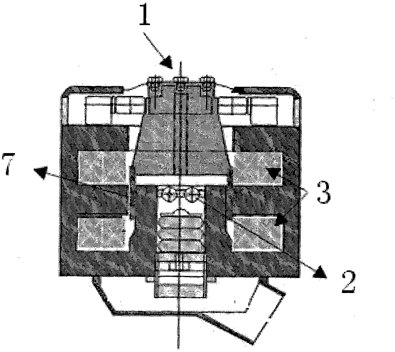
[0026] An electric vibrating table includes a table body 1, a magnetic cylinder 2, an excitation winding 3, a moving coil frame 5, a driving coil 6, a moving coil 7, a suspension support guide device and a cooling device, and the bottom of the moving coil frame 5 is provided with The metal bobbin 4 of the wall barrel type, the metal bobbin 4 is rolled by stainless steel plate, the cylinder surface of the stainless steel bobbin is uniformly provided with through holes 8, the stainless steel bobbin 4 and The driving coil 6 is coaxial, located on the outer or inner circumference of the driving coil 6, and the stainless steel plate and the driving coil 6 are bonded with high-temperature epoxy resin, and the two stainless steel wrapping plates of the stainless steel bobbin 4 are separately arranged on the driving coil 6 The outer and inner sides, ie the outer and inner circumferences which wrap around the drive coil 6, cons...
Embodiment 2
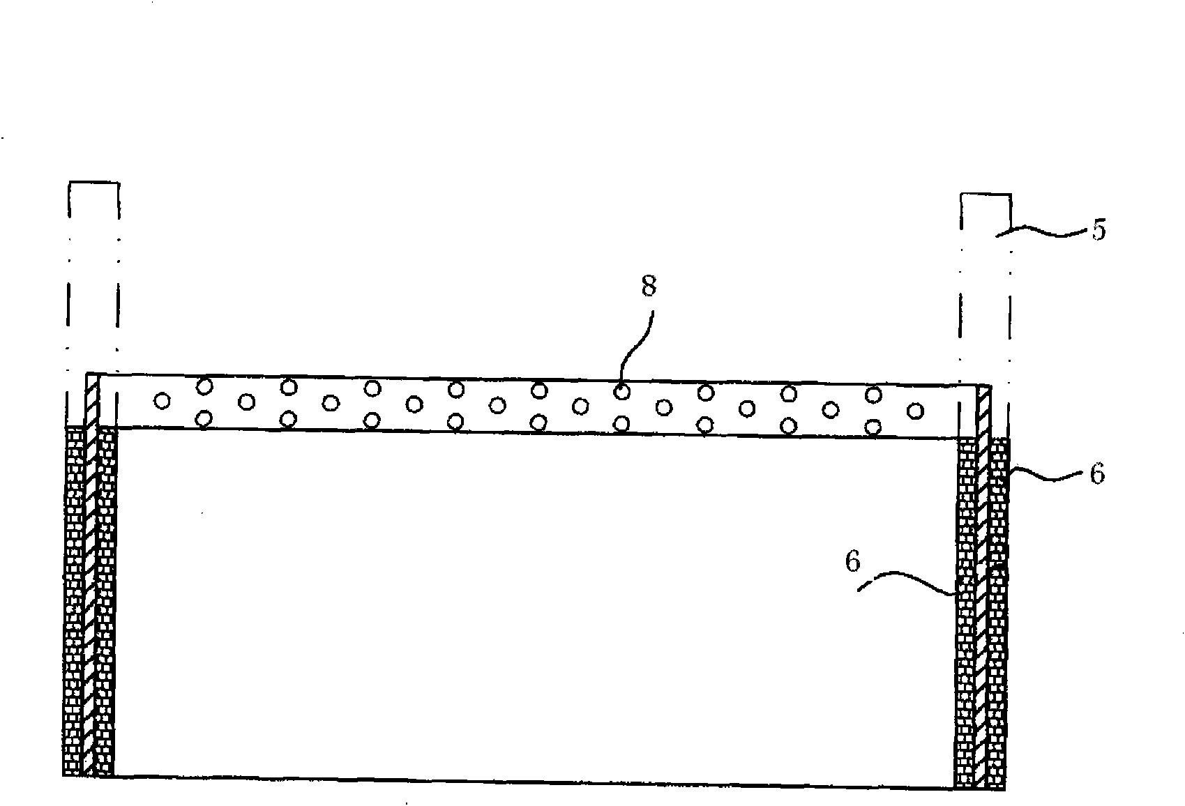
[0027] Embodiment two: see attached image 3 as shown,
[0028] An electric vibrating table, the difference from the first embodiment is: the stainless steel bobbin 4 is clamped and embedded between the inner winding and the outer winding of the driving coil 6 . During production, the inner coil winding of the drive coil 6 is wound first, and then the inner coil winding is wrapped with a stainless steel bobbin 4, and then the outer coil winding of the drive coil 6 is wound on the outer circumference of the stainless steel bobbin 4 to form A separate winding part. When connecting the winding components with the moving coil bobbin 5, an embedded groove corresponding to the upper end surface of the stainless steel bobbin 4 can be provided on the lower end surface of the moving coil bobbin 5, and the moving coil bobbin 5 is sleeved on the upper end of the stainless steel bobbin 4 On the part, it is glued and connected with the stainless steel bobbin 4 through high-temperature ep...
PUM
 Abstract
Description
Claims
Application Information
 - R&D
- Intellectual Property
- Life Sciences
- Materials
- Tech Scout
- Unparalleled Data Quality
- Higher Quality Content
- 60% Fewer Hallucinations
Browse by: Latest US Patents, China's latest patents, Technical Efficacy Thesaurus, Application Domain, Technology Topic, Popular Technical Reports.
© 2025 PatSnap. All rights reserved.Legal|Privacy policy|Modern Slavery Act Transparency Statement|Sitemap|About US| Contact US: help@patsnap.com


