Unmanned aerial vehicle route dynamic planning method based on A* search

A technology of dynamic programming and unmanned aerial vehicles, which is applied in the direction of vehicle position/route/height control, non-electric variable control, control/regulation system, etc., and can solve problems such as poor adaptability

Active Publication Date: 2016-11-16
NORTHWESTERN POLYTECHNICAL UNIV
View PDF4 Cites 30 Cited by
  • Summary
  • Abstract
  • Description
  • Claims
  • Application Information

AI Technical Summary

Problems solved by technology

[0005] In order to overcome the shortcomings of the existing methods in the complex environment where there are elongated pol

Method used


Image

  • Unmanned aerial vehicle route dynamic planning method based on A* search
  • Unmanned aerial vehicle route dynamic planning method based on A* search
  • Unmanned aerial vehicle route dynamic planning method based on A* search

Examples


Embodiment Construction

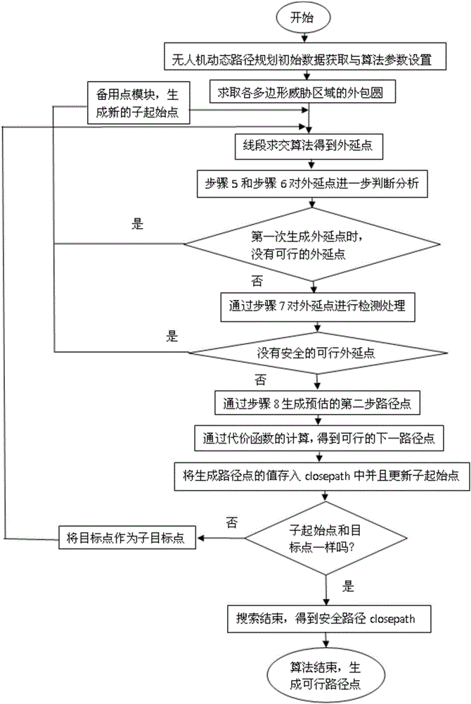
[0084] refer to Figure 1-6 . The specific steps of the UAV path dynamic planning method based on A* search in the present invention are as follows:

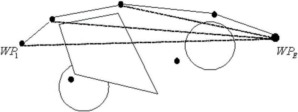
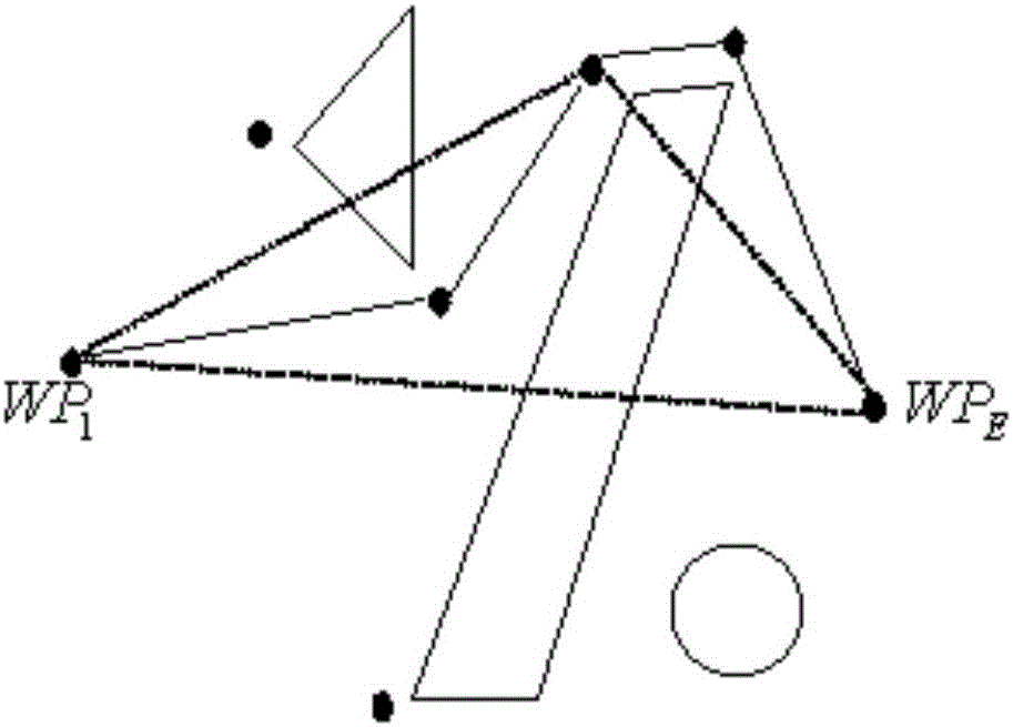
[0085] The simulation is carried out in a two-dimensional planar rectangular planning space of {(x,y)|-110km≤x≤110km, -90km≤y≤90km}, which includes circles, polygons, and threat areas superimposed on each other.

[0086] Step 1: Initial data acquisition and algorithm parameter setting for UAV dynamic path planning.

[0087] 1) Initial data acquisition.

[0088] ①Get the initial position coordinate WP of the drone 1 (50,80) and target position coordinates WP E (-110,-90);

[0089] ② The parameter data of the threat area includes: the number of threat areas modeled as circles M = 13, each circular threat area C i The center and radius of the circle (x i ,y i ,r i ), where i=1,2,...,M; the number of threat zones modeled as polygons N=10, the number of vertices of each polygon threat zone (n 1 ,n 2 ,...,n N ), each polyg...


PUM


Abstract

The invention discloses an unmanned aerial vehicle route dynamic planning method based on A* search, which is used for solving the technical problem that the existing method has poor adaptability for the situation that long-strip shaped polygonal threatening regions or no-fly zones exist in the complex environment. The unmanned aerial vehicle route dynamic planning method comprises the steps of: constructing circumscribed circles of polygonal threatening regions or no-fly zones at first, and judging whether a line segment formed by a starting point and a target point intersects with each polygonal circumscribed circle; further judging whether the line segment and the polygonal threatening regions or no-fly zones have an intersection point or not if the line segment intersects with the polygonal circumscribed circles; and if so, planning and generating a route directly avoiding the polygonal threatening regions or no-fly zones based on an A* search algorithm, wherein a dead zone escaping and two-step optimizing strategies is adopted during the route planning process for planning and generating route points in sequence. The unmanned aerial vehicle route dynamic planning method can adapt to the situation that the long-strip shaped polygonal threatening regions or no-fly zones exist in the complex environment, and can adapt to the situation that the circular or polygonal threatening regions or no-fly zones are overlapped with one another.

Description

technical field [0001] The invention relates to a dynamic planning method for a path of an unmanned aerial vehicle, in particular to an A* search-based dynamic planning method for a path of an unmanned aerial vehicle. Background technique [0002] UAV path planning is to find an optimal or feasible path from the starting point to the end point for the UAV under given constraints within the planning area. When there is a sudden danger / threat that needs to be avoided or a task change occurs during the flight of the UAV, a safe and feasible path needs to be dynamically generated. The path dynamic programming problem is essentially a multi-objective optimization problem with many constraints. [0003] The document "Self-optimized A* UAV route planning algorithm based on Laguerre graph, Systems Engineering and Electronic Technology, 2015, Vol.37(3), p577-582" discloses a LA-Star algorithm for UAV route planning. The algorithm first simplifies the polygonal threat area and the p...

Claims


Application Information

Patent Timeline
IPC IPC(8): G05D1/10G01C21/20
CPCG01C21/20G05D1/101
Inventor 谭雁英周军李洋祝小平蒋瑞民张波
Owner NORTHWESTERN POLYTECHNICAL UNIV
Why Eureka
Try Eureka