Multi-camera calibration and alignment fitting method

A multi-camera, calibration technology, applied in image data processing, instruments, calculations, etc., can solve the problem of expensive hardware design, and achieve the effect of simplifying the configuration adjustment process, simplifying derivation, and eliminating system errors

Active Publication Date: 2016-11-16
SHENZHEN VISION DRAGON INTELLIGENT SENSOR CO LTD
View PDF6 Cites 34 Cited by
  • Summary
  • Abstract
  • Description
  • Claims
  • Application Information

AI Technical Summary

Problems solved by technology

[0002] The high-precision calibration of a multi-camera system is a relatively complex task in the field of computer vision. It is often necessary to design high-precision and high-stability hardware to ensure the stability of the entire measurement system for a long time. For complex multi-camera systems, the design of this hardware cost will be very expensive

Method used


Image

  • Multi-camera calibration and alignment fitting method
  • Multi-camera calibration and alignment fitting method
  • Multi-camera calibration and alignment fitting method

Examples


Embodiment 1

[0045] In this embodiment, the multi-camera calibration and alignment bonding method, the calibration process includes:

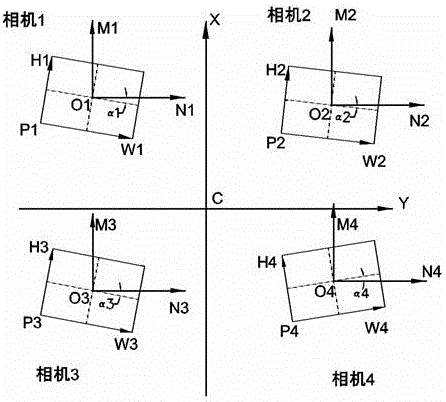
[0046] In the first stage, the internal parameters of each camera in the camera group and the camera installation angle are calibrated.

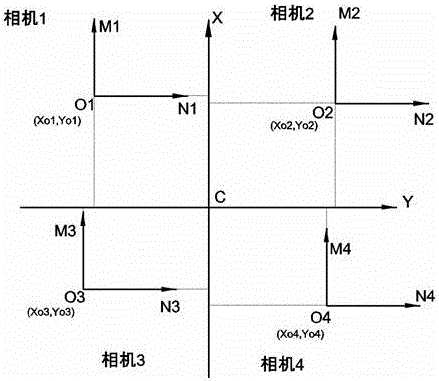
[0047] In the second stage, the position of the rotation center of the deviation correction platform in the output coordinate system of each camera in the camera group is calibrated, and the rotation coordinate system is established according to the rotation center of the deviation correction platform as a certain point after zeroing.

[0048] The third stage of calibration is based on the coincidence of the rotating coordinate systems of the first camera group and the second camera group, and the first camera group is mapped and calibrated by the second camera group.

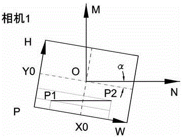
[0049] In this embodiment, the first-stage calibration adopts a two-point calibration method. The two-point calibration method is as follows, the image c...

Embodiment 2

[0064] Such as Figure 6 As shown, the multi-camera calibration and alignment bonding method in this embodiment, the calibration process includes: the second camera group calculates the center A1 of the object to be bonded, the first camera group calculates the center A2 of the target object; The deviation angle between the bonding object and the target object , the deviation distance A between the center of the fitting and the center of the target object, the deviation distance A(Xa,Ya) rotation deviation angle After point B(Xb,Yb), is the offset of an alignment fit, and the calculation algorithm is:

[0065] .

[0066] Alignment and fit correction amount calculation algorithm: Relative coordinate algorithm is adopted, that is, the deviation distance can be converted into a point in the rotating coordinate system. One-time alignment and fitting algorithm, which calculates the offset to be run, runs in place and fits once, and does not need to collect images again to ...


PUM


Abstract

The invention discloses a multi-camera calibration and alignment fitting method. A posture of a target object is observed by using a first camera group; a posture of a fitting object is observed by using a second camera group; and rotating coordinate systems of the two camera groups coincide. A calibration process comprises a first calibration stage, a second calibration stage and a third calibration stage. In the first calibration stage, internal parameters and a camera mounting angle of each camera in the camera groups are calibrated; in the second calibration stage, the position, in an output coordinate system of each camera in the camera groups, of a rotating center of a correction platform is calibrated and the rotating coordinate systems are established according to the condition that the rotating center of the correction platform is a fixed point after returning to zero; and in the third calibration stage, mapping and calibration are performed: the first camera group is mapped and calibrated by the second camera group according to the condition that the rotating coordinate systems of the first camera group and the second camera group coincide.

Description

technical field [0001] The invention relates to a multi-camera calibration and alignment bonding method. Background technique [0002] The high-precision calibration of a multi-camera system is a relatively complex task in the field of computer vision. It is often necessary to design high-precision and high-stability hardware to ensure the stability of the entire measurement system for a long time. For complex multi-camera systems, the design of this hardware The cost will be very expensive. Contents of the invention [0003] In view of the above problems, the present invention provides a multi-camera calibration and alignment bonding method. [0004] In order to achieve the above-mentioned purpose, in the multi-camera calibration and alignment bonding method of the present invention, the posture of the target object is observed by a group of first camera groups, the posture of the object is observed by a group of second camera groups, and the rotation of the two groups o...

Claims


Application Information

Patent Timeline
Patent Type & Authority Applications(China)
IPC IPC(8): G06T7/00
CPCG06T2207/30208
Inventor 何伟丁少华
Owner SHENZHEN VISION DRAGON INTELLIGENT SENSOR CO LTD
Why Eureka
Try Eureka