
Key structure and portable computer using the same

A portable, key-press technology, applied in circuits, electric switches, electrical components, etc., can solve problems such as inability to store key structures, poor sensitivity, and difficult assembly of scissor foot structures

Active Publication Date: 2016-11-16
LITE ON TECH CORP
View PDF5 Cites 19 Cited by
  • Summary
  • Abstract
  • Description
  • Claims
  • Application Information

AI Technical Summary

Problems solved by technology

However, the scissor foot structure is not easy to assemble, and the pressing stroke is relatively high, so it is not suitable for thin keyboards
At the same time, when the button cap is pressed, the downward force needs to be transmitted to the film circuit board made of double-layer circuit through the elastic member. If the downward force is too small, it will not be easy to make the double-layer circuit contact, so the sensitivity is poor.
In addition, the existing button structure cannot be stored in the non-use state to reduce the height of the structure. Today, as portable computers emphasize ultra-thin thickness, it is necessary to develop a new button structure to reduce the overall thickness of the portable computer

Method used


Image

  • Key structure and portable computer using the same
  • Key structure and portable computer using the same
  • Key structure and portable computer using the same

Examples


Embodiment Construction

[0114] The following is a detailed description of the embodiments, which are only used as examples, and are not intended to limit the scope of protection of the present invention.

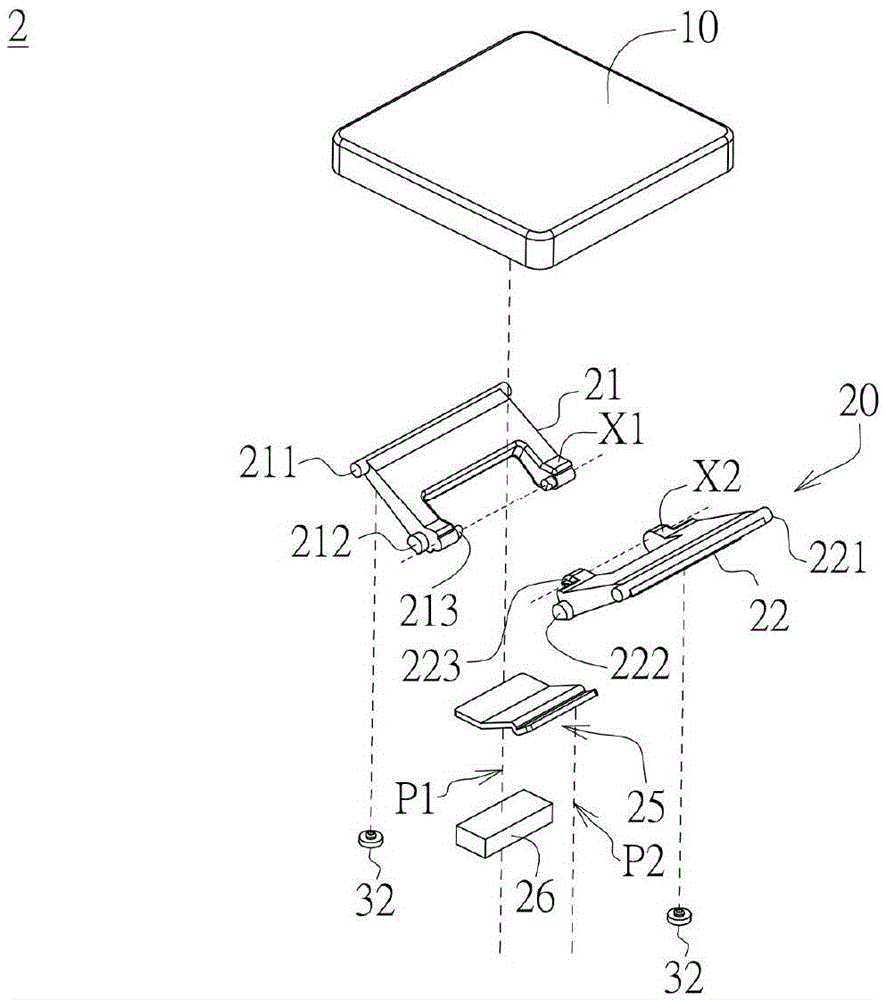
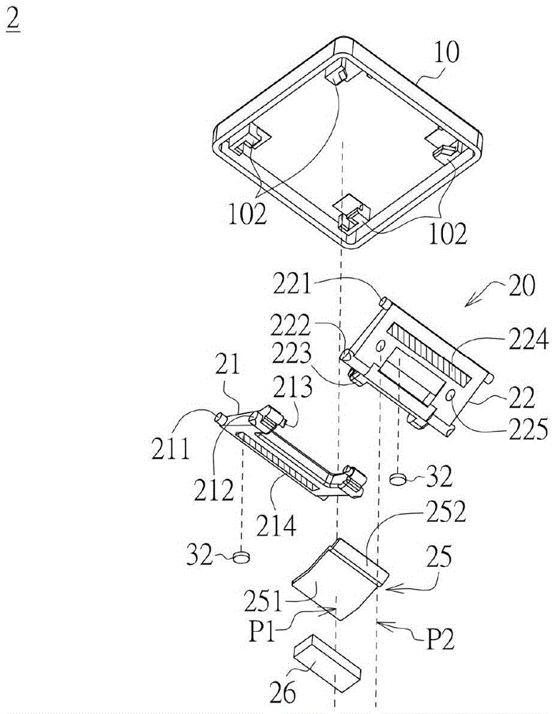
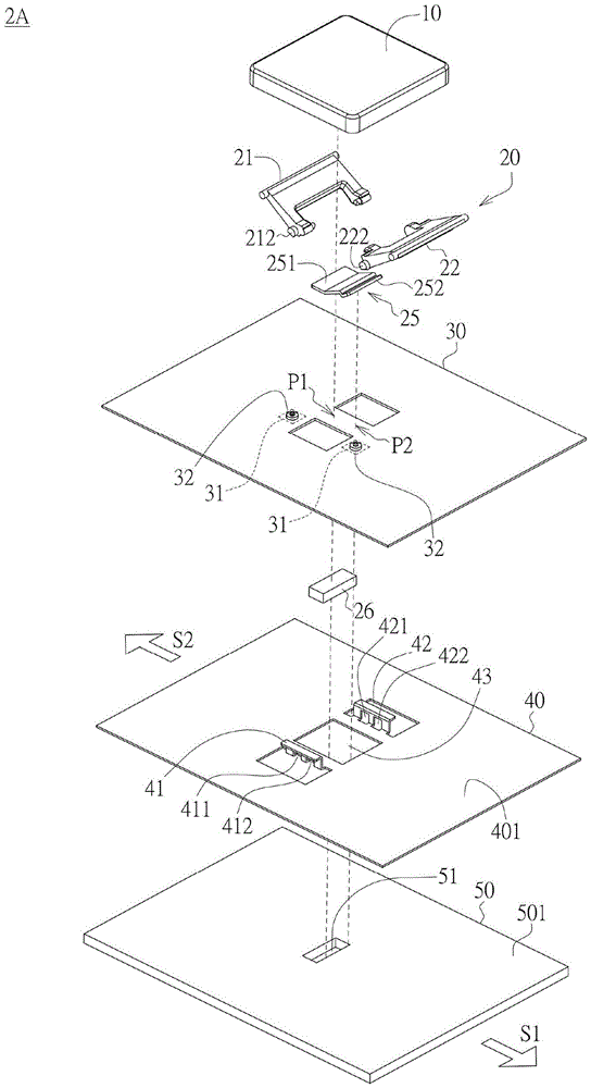
[0115] Figure 1~2 The schematic diagrams of the top view and bottom view of the decomposed components of the key structure 2 according to an embodiment of the present invention are respectively shown. Please refer to figure 1 , the key structure 2 includes a key cap 10 and a pivot assembly 20 . The pivot assembly 20 is disposed under the keycap 10 . The pivot assembly 20 includes a first pivot member 21 and a second pivot member 22 intersecting in a V shape. One end of the first pivot member 21 has a first connecting rod 211 , and the other end has a first shaft fixing portion 212 and a first rotating shaft X1 . In addition, one end of the second pivot member 22 has a second connecting rod 221 , and the other end has a second shaft fixing portion 222 and a second rotating shaft X2 . In addit...


PUM


Abstract

The invention provides a key structure and a portable computer using the same. The key structure includes a key cap, a bridge assembly, a first supporting part, a second supporting part, an attractable element and a magnet. The bridge assembly includes first and second hinge parts. One end of the first hinge part has a first link bar, and the other end has a first pivot coupling portion and a first shaft having a first connecting portion. One end of the second hinge part has a second link bar, and the other end has a second pivot coupling portion and a second shaft having a second connecting portion coupled to the first connecting portion. The two connecting portions are engaged with each other to connect the first and second hinge parts. The first and second supporting parts are respectively coupled to both ends of the shaft fixing portion. The attractable element is disposed below the bridge assembly and the attractable element has a first and second end movable relative to an axis to a respective first and second attractable sites. The magnet may be moved back and forth to a position below the first or second attractable position, the first or second end of the attractable element being magnetically attracted to move to the first or second attractable position when the magnetic element is respectively below the first or second attractable position.

Description

technical field [0001] The invention relates to a button structure, and in particular to a lightweight and thin-designed button structure and a portable computer using the button structure. Background technique [0002] The existing key structure adopts an elastic member to provide an elastic restoring force of the key cap, and supports the key cap with a scissor foot structure, so that the key cap can return to the position before being pressed. However, the scissor foot structure is not easy to assemble, and the pressing stroke is relatively high, so it is not suitable for thin keyboards. At the same time, when the push cap is pressed, the downward force needs to be transmitted to the film circuit board made of double-layer circuit through the elastic member. If the downward force is too small, it will not be easy to make the double-layer circuit contact, so the sensitivity is poor. In addition, the existing button structure cannot be stored in the non-use state to reduce...

Claims


Application Information

Patent Timeline
Patent Type & Authority Applications(China)
IPC IPC(8): H01H3/12G06F1/16
CPCG06F1/1662H01H3/125H01H13/7065H01H2231/002H01H2221/04
Inventor 陈俊麟郭治仁颜铭甫许国辉
Owner LITE ON TECH CORP
Learn More