Improvements in or relating to air-bags
A technology of airbags and gases, applied in textiles, fabrics, multi-strand fabrics, etc.
- Summary
- Abstract
- Description
- Claims
- Application Information
AI Technical Summary
Problems solved by technology
Method used
Image

Examples
Embodiment Construction
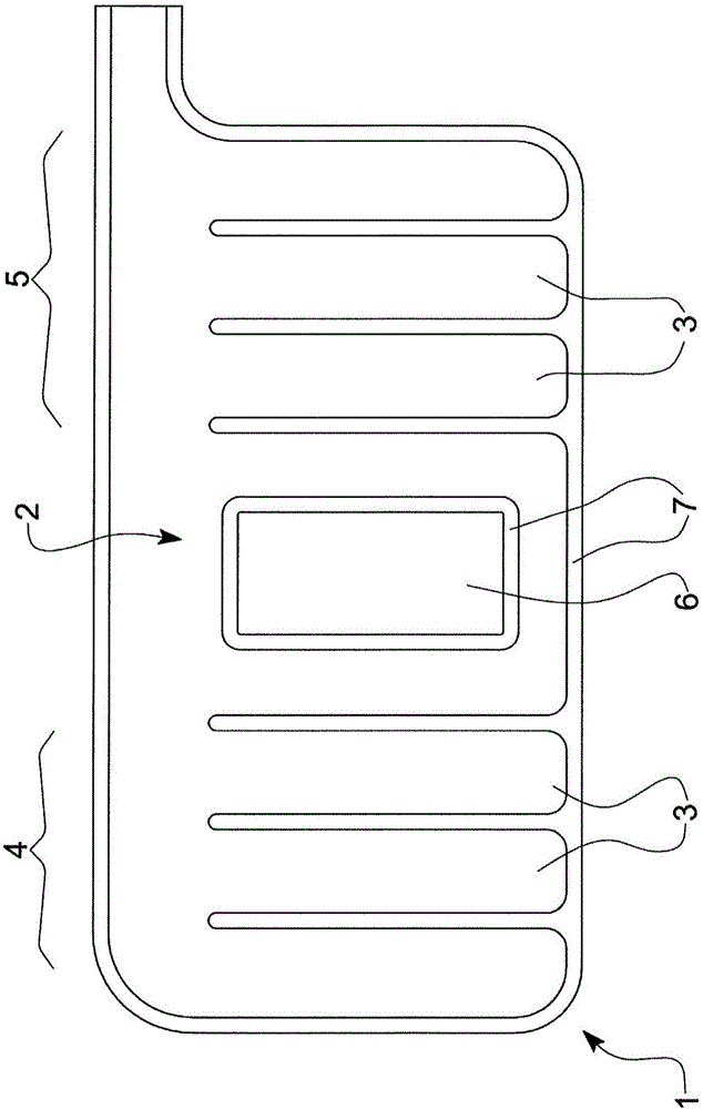
[0030] first reference figure 2 , showing a representative of a conventional non-inflatable region of an IC airbag, such as can be used in figure 1 A known airbag 1 is shown.
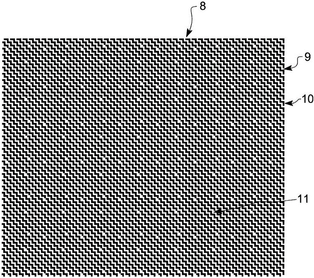
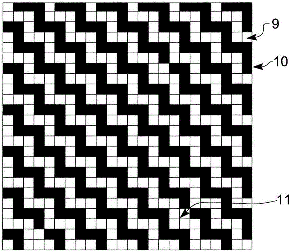
[0031] figure 2 A grid of cells 8 is shown, with some cells represented in white 9 and others shaded 10 . figure 2 A schematic representation of the weave of one of the fabric layers making up the non-inflatable region of the airbag. The grid of cells corresponds to the warp and weft threads of the fabric layer, the vertical columns of the grid representing the warp threads and the horizontal rows of the grid representing the weft threads (or vice versa).
[0032] if figure 2 The layer shown is considered as the upper layer of a two layer fabric, the shaded cells 10 represent the intersections where the warp threads pass above the weft threads, and the white cells represent the intersection points where the warp threads pass below the weft threads. A technically savvy reader should recognize th...
PUM
 Abstract
Description
Claims
Application Information
PatSnap Eureka turns technology decisions into work you can execute. Powered by our Innovation Knowledge Graph, it runs expert workflows across engineering, life sciences, materials and intellectual property. Get your review-ready output in minutes.


