Supercharge Your Innovation With Domain-Expert AI Agents!

Fastening device for heat shield

A fastening device and fastening technology, which is applied in the direction of aircraft power devices, aircraft power device components, thin plate connections, etc., can solve problems such as inconvenience

Active Publication Date: 2019-06-07
AIRCELLE
View PDF5 Cites 0 Cited by
  • Summary
  • Abstract
  • Description
  • Claims
  • Application Information

AI Technical Summary

Problems solved by technology

Therefore, this operation requires a lot of time and accuracy of the operator for each fastening point, which is a disadvantage that causes further inconvenience because this operation has to be repeated many times

Method used


Image

  • Fastening device for heat shield
  • Fastening device for heat shield
  • Fastening device for heat shield

Examples


Embodiment Construction

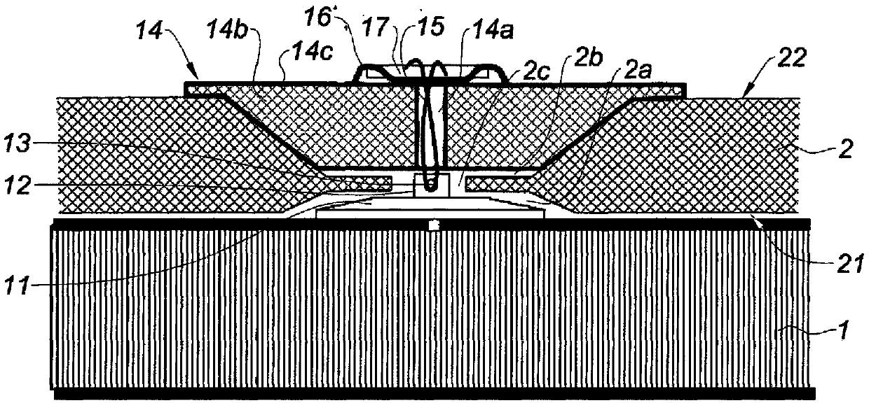
[0038] figure 1 Is a sectional view of a part of the Internal Fixing Structure 1 (IFS) of a turbojet engine nacelle, a heat shield 2 is fastened to this illustrated part by means of a plurality of fastening means. Pad 2 comprises a surface in contact with structure 1 (referred to as inner surface 21 ) and an opposite surface (referred to as outer surface 22 ).

[0039] According to the invention, at least one means for fastening the pad 2 to the structure 1 comprises a fastening base 11 . The base is fastened to the fixing structure 1 , for example by gluing, and is equipped with hooking structures 12 . In the example, the hooking structure 12 is in the form of an eye bolt 13 protruding in a direction substantially perpendicular to the surface of the structure 1 to which the base 11 is attached.

[0040] The anti-heat mat 2 covers the base 11 in an opening or cavity 2 a with a shape formed over the thickness of the mat 2 that is substantially complementary to the base 11 . ...


PUM


Abstract

The invention relates to a structural assembly (1) of an aircraft turbojet engine nacelle and a thermal protection mat (2) attached to the structure (1), the mat being attached to said structure (1) via at least one attachment device, the attachment device comprising an attachment base (11) rigidly connected to the structure (1), said attachment base (11) being rigidly connected to one end of a link (15), said link (15) passing through the mat (2) via a passage (2a, 2b, 2c) provided in the mat (2), and being rigidly connected at the other end of same to a retaining button (16), the assembly being characterised in that the attachment device comprises a removable spacer (14) inserted at least partially into a recess (2b) of the thermal protection mat (2), the spacer being disposed between the thermal protection mat (2) and the retaining button (16) and having a through-hole (14a) through which the link (15) can pass, the spacer being held in position by the retaining button (16).

Description

technical field [0001] The invention relates to a device for fixing a heat protection mat to an internal fixed structure of a turbojet nacelle. Background technique [0002] The aircraft is powered by one or several turbojet engines, each engine being housed in a nacelle. [0003] The nacelle generally has a generally tubular structure comprising an air intake upstream of the turbojet engine, a middle assembly intended to surround the turbojet fan and an aft assembly which may incorporate thrust reverser means and is intended to surround the combustion chamber, and all or Part of the compressor stage and turbojet turbine, the nacelle usually terminates in a jet nozzle whose outlet is located downstream of the turbojet engine. [0004] The modern nacelle is designed to accommodate a bypass turbojet engine which, on the one hand, is able to generate a thermal flow (also called main flow) from the combustion chamber of the turbojet engine. The compartments circulate in the sp...

Claims


Application Information

Patent Timeline
Patent Type & Authority Patents(China)
IPC IPC(8): B64D29/06
CPCF16B5/0692B64C1/403F16B5/0642
Inventor 塞德里克·雷诺
Owner AIRCELLE
Features
  • R&D
  • Intellectual Property
  • Life Sciences
  • Materials
  • Tech Scout
  • Unparalleled Data Quality
  • Higher Quality Content
  • 60% Fewer Hallucinations
Learn More