Dust-removing mop

A technology of mop and connecting parts, which is applied in the direction of cleaning carpets, floors, cleaning equipment, etc., and can solve problems such as troublesome operation

Inactive Publication Date: 2016-11-23
许敏修
View PDF8 Cites 4 Cited by
  • Summary
  • Abstract
  • Description
  • Claims
  • Application Information

AI Technical Summary

Problems solved by technology

[0004] When performing dust removal, the user holds the handle 230 and moves forward or backward, and since the dust removal paper 300 below the base plate 210 is flat against the ground, the dust will be collected on the front or rear side of the base plate 210, and If these accumulated dusts are electrostatically adsorbe

Method used


Image

  • Dust-removing mop
  • Dust-removing mop
  • Dust-removing mop

Examples


Embodiment Construction

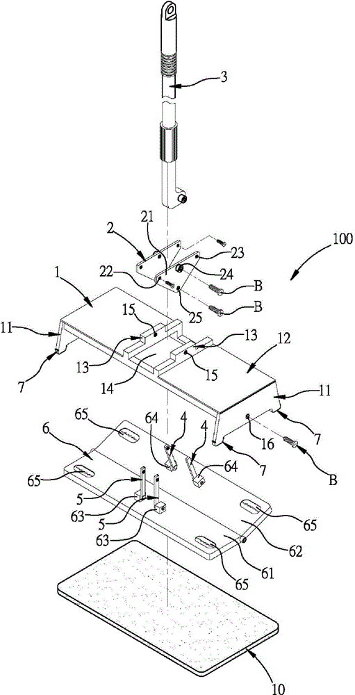
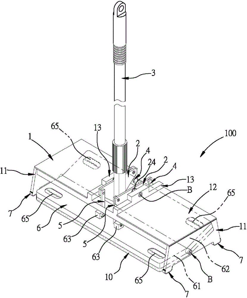
[0056] Please also see Figure 2 to Figure 7 As shown, the dust removal mop 100 of the present invention includes a base 1 , two first connectors 2 , a handle 3 , two second connectors 4 , two third connectors 5 , and a board 6 .

[0057] The base 1 has two side plate portions 11, a flat plate portion 12, and two raised portions 13. The two side plate portions 11 extend downward from both axial ends of the plate portion 12, and the center of the plate portion 12 has a slot 14. The two protruding parts 13 are respectively located at both ends of the slot 14, and the axial direction of each protruding part 13 is parallel to the radial direction of the flat plate part 12, and a first pivot joint is formed at the center of each protruding part 13. Holes 15 , and a second pivot hole 16 is formed at the center of each side plate portion 11 .

[0058] Each first connector 2 can be an inverted triangle, and each first connector 2 has a body 21, a front upper connection hole 22, a rea...


PUM


Abstract

The invention provides a dust-removing mop. When the dust-removing mop moves frontward and applies force, each first connecting piece is forward and upward inclined and the lower surface of a second plate part is in tight contact with the ground; meanwhile, the front upper end of each first connecting piece is used for upward lifting a first plate part to be far away from the ground through each third connecting piece, so that impurities including dust and the like on the ground are pushed forward to abut against the lower side of the first plate part, and forward dust collection work is carried out; when the dust-removing mop moves backward and applies the force, each first connecting piece is backward and upward inclined, and the first plate part is pushed downward to abut against the lower side of the first plate part, so as to be in tight contact with the ground; the concentrated impurities including the dust and the like are pressed and abutted between the first plate part and the ground, and the impurities are adsorbed to realize dust removing work; meanwhile, the second plate part is lifted upward, and the impurities including the dust and the like on the ground are pushed backward to abut against the lower side of the second plate part and then backward dust collection work is carried out, and so on; and therefore, the dust removing effect can be realized through forward movement and backward movement.

Description

technical field [0001] The invention relates to a dust-removing device, especially a dust-removing mop that can swing back and forth to remove dust and the like when moving forward and backward. Background technique [0002] General dust mop 200, such as figure 1 As shown, it includes a bottom plate 210 , a protruding shaft 220 , and a handle 230 . [0003] The protruding shaft 220 can be disposed above the bottom plate 210 , and the handle 230 can be pivotally connected with the protruding shaft; and a dust removal paper 300 can be covered under the bottom plate 210 . [0004] When performing dust removal, the user holds the handle 230 and moves forward or backward, and since the dust removal paper 300 under the base plate 210 is flat against the ground, the dust will be collected on the front or rear side of the base plate 210, and If these accumulated dusts are electrostatically adsorbed by the dust-removing paper 300, the bottom plate 210 must be raised forwards and th...

Claims


Application Information

Patent Timeline
IPC IPC(8): A47L13/20A47L13/24A47L13/42
Inventor 许敏修
Owner 许敏修
Why Eureka
Try Eureka