Corrector for joint replacement

A joint replacement and corrector technology, which is applied in the field of medical devices for total knee replacement surgery, can solve the problems that the parallel line and the condylar line cannot be accurately consistent, and there is no adjustment tool, so as to achieve the effect of improving the calibration accuracy and being easy to grasp

Inactive Publication Date: 2017-10-24
青岛山大齐鲁医院(山东大学齐鲁医院(青岛))
View PDF6 Cites 0 Cited by
  • Summary
  • Abstract
  • Description
  • Claims
  • Application Information

AI Technical Summary

Problems solved by technology

[0005] Therefore, the technical problem to be solved by the present invention is to overcome that when the parallel line of the line d calibrated by the calibration tool in the prior art is not parallel to the condylar line, there is no special adjustment tool for adjustment, which requires human eyes to estimate, resulting in The technical defect that the parallel line of the calibrated line d cannot be exactly consistent with the condylar line, so as to provide a joint replacement that can accurately adjust the parallel line of the above line d so that the calibrated line d is parallel and consistent with the condylar line Correction

Method used


Image

  • Corrector for joint replacement
  • Corrector for joint replacement
  • Corrector for joint replacement

Examples


Embodiment 1

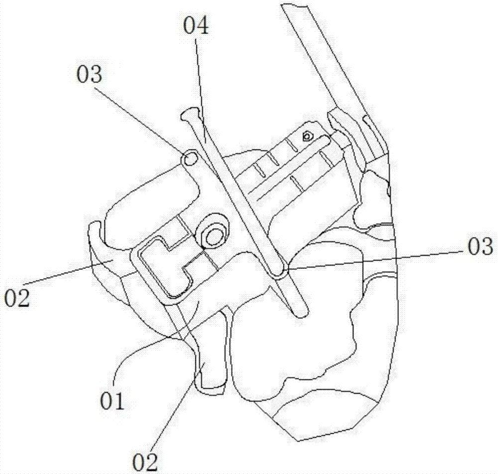
[0049] This embodiment provides a corrector for joint replacement, such as Figure 4-5 As shown, including a body 10, a pair of reference holes 1 and several pairs of adjustment holes 2, 3, 4, 5, 6, 7 are provided on the body 10, and the distance between the pairs of reference holes 1 is set so that it It is suitable to be sleeved on the fixed nails to be adjusted at the same time; the line connecting the centers of the paired reference holes 1 and the paired adjustment holes 2, 3, 4, 5, 6, 7 closest to their inclination The angle difference between the lines connecting the centers of the circles is ≤2°, and the angle difference between the lines connecting the centers of any two pairs of the adjustment holes 2, 3, 4, 5, 6, and 7 with the closest inclination degree is ≤ 2°; Including an inclinometer structure installed on the body 10, used to measure the angle difference between the condylar line and the line connecting the centers of the paired reference holes 1; The first s...

Embodiment 2

[0060] This embodiment provides a method for using a corrector for joint replacement, refer to Figure 4 shown, including the following steps:

[0061] S1 Set a pair of reference holes 1 on the body 10 on a pair of fixing nails to be adjusted;

[0062] S2 uses the tilt measuring structure to measure the angle difference between the condyle line and the line connecting the centers of a pair of reference holes 1, and finds the line connecting the centers of the circle and the line connecting the centers of the reference holes 1 having the same or the closest angle difference A pair of adjustment holes;

[0063] S3 Reset new fixing nails at the found positions of the pair of adjustment holes 2, 3, 4, 5, 6, 7.

[0064] The use method of the corrector for joint replacement in this embodiment can more accurately adjust the setting position of the fixing nails when the line connecting the two fixing nails is not parallel to the condylar line, so that the adjusted connecting line of...


PUM


Abstract

The invention provides a corrector for joint replacement and a use method thereof. The corrector for joint replacement comprises a corrector body which is provided with at least one pair of datum holes and multiple pairs of adjusting holes; wherein an angle difference between the connection line of circle centers of the paired datum holes and the connection line of circle centers of the paired adjusting holes of which the inclined degree is the most proximate to that of the datum holes is smaller than or equal to two degrees; an angle difference between the connection lines of the circle centers of every two pairs of the adjusting holes with the most proximate inclined degrees is smaller than or equal to two degrees, and the corrector for joint replacement further comprises an inclination angle measuring structure. Compared with human eye pre-estimation in the prior art, according to the corrector for joint replacement, mastering is easier, and the error can be controlled within two degrees; by taking two completely adjusted fastening nails as the basis, a front tangent plane and a rear tangent plane can be effectively controlled to be basically parallel to a condyle through line, improper extorsion osteotomy of condyle before and after a thigh bone is avoided, precise osteotomy is achieved, and the clinical curative effect is improved.

Description

technical field [0001] The invention relates to the technical field of medical instruments for total knee replacement surgery, in particular to a corrector for total knee external rotation joint replacement. Background technique [0002] With the continuous development and progress of medical technology, artificial knee replacement surgery has become one of the routine treatments for knee joint lesions. Artificial knee replacement is the use of artificial joint prosthesis to replace the damaged joint to restore and improve joint function and improve the quality of life. Due to the short course of artificial knee replacement and obvious pain relief effect, it is accepted by more and more doctors and patients. In artificial knee arthroplasty, an osteotomy of the distal femur is required to obtain a femoral model for the artificial joint prosthesis, such as figure 1 As shown, the distal end of the femur is firstly osteotomized to form a vertical section a, and then two flat s...

Claims


Application Information

Patent Timeline
Patent Type & Authority Patents(China)
IPC IPC(8): A61B17/15A61B17/56
CPCA61B17/155A61B17/56A61B2017/564
Inventor 张鹏孔杰杜建春万连平刘泽淼
Owner 青岛山大齐鲁医院(山东大学齐鲁医院(青岛))
Why Eureka
Try Eureka