Oil pipe outer pipe wall cleaning machine

A technology of outer tube wall and cleaning machine, which is applied in the direction of cleaning hollow objects, cleaning methods and utensils, chemical instruments and methods, etc., which can solve the problems of low flushing efficiency and achieve the effect of automatic and efficient cleaning

Active Publication Date: 2016-11-23
蚌埠格识知识产权运营有限公司
View PDF6 Cites 2 Cited by
  • Summary
  • Abstract
  • Description
  • Claims
  • Application Information

AI Technical Summary

Problems solved by technology

[0003] At present, the tubing cleaning of oil wells adopts an open type

Method used


Image

  • Oil pipe outer pipe wall cleaning machine
  • Oil pipe outer pipe wall cleaning machine
  • Oil pipe outer pipe wall cleaning machine

Examples


Embodiment Construction

[0018] In order to make the technical means, creative features, goals and effects achieved by the present invention easy to understand, the present invention will be further elaborated below in conjunction with the embodiments.

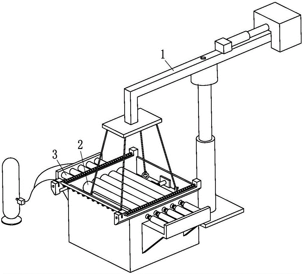
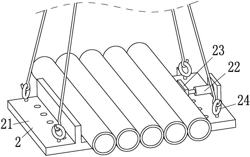
[0019] like figure 1 , figure 2 , image 3 , Figure 4 and Figure 5 As shown, a cleaning machine for the outer pipe wall of the oil pipe according to the present invention includes a hoisting device 1 , a pipe clamping device 2 and a cleaning device 3 .

[0020] The lifting device 1 includes a lifting hydraulic cylinder 11, a rotating motor 12, a cantilever 13, a lifting plate 14, a hook 15, a weight adjusting cylinder 16 and a counterweight 17, and the top of the lifting hydraulic cylinder 11 is fixedly connected with a rotating motor 12. The middle part of the cantilever 13 is installed on the main shaft of the rotating motor 12; the cantilever 13 includes a left cantilever 131 and a right cantilever 132, and the left cantilever 131 includes a...


PUM


Abstract

The invention relates to the field of petroleum devices, in particular to an oil pipe outer pipe wall cleaning machine. The oil pipe outer pipe wall cleaning machine comprises a hoisting device, a pipe clamping device and a cleaning device. The hoisting device comprises a lifting hydraulic cylinder, a rotating motor, a suspension arm, a hoisting plate, a hoisting hook, a weight regulating cylinder and a balancing weight. The pipe clamping device comprises a pipe containing plate, a push cylinder, a push plate and a hoisting ring. The cleaning device comprises a cleaning bin, an external cleaning device, a heating furnace and a cleaning pump. The oil pipe outer pipe wall cleaning machine can automatically and efficiently wash oil pipe outer walls.

Description

technical field [0001] The invention relates to the field of petroleum equipment, in particular to a cleaning machine for outer pipe walls of oil pipes. Background technique [0002] With the rapid development of my country's economy, the contradiction between energy shortage, environmental pollution and economic development has become increasingly prominent, so the country advocates environmental protection, energy-saving projects with independent intellectual property rights. Entering the 21st century, the relevant state departments have proposed a series of new concepts of environmental protection measures such as environmental protection, energy conservation and emission reduction, and at the same time shut down a group of small and medium-sized enterprises that are not suitable for continued development, such as small scale, high energy consumption, and large environmental pollution, and vigorously improve the national economy. living environment. The petroleum industr...

Claims


Application Information

Patent Timeline
IPC IPC(8): B08B9/023
CPCB08B9/023B08B2209/02
Inventor 胡来源
Owner 蚌埠格识知识产权运营有限公司
Why Eureka
Try Eureka