
Self-positioning auxiliary code scanning mechanism

A self-positioning and code scanning technology, applied in the field of identification, can solve the problems of easily damaged product surface, difficulty in manual tearing of film, and high product stacking, so as to avoid artificial defects, improve the grasping effect, and speed up the grasping speed.

Inactive Publication Date: 2016-11-23
SUZHOU LANGKUN AUTOMATION EQUIP CO LTD
View PDF11 Cites 4 Cited by
  • Summary
  • Abstract
  • Description
  • Claims
  • Application Information

AI Technical Summary

Problems solved by technology

[0002] Before many large-scale products are put into storage or used, because the external carrier packaging is the same, they need to be sorted and identified. Currently, manual operations are generally used. However, due to the high stacking of products, there is great inconvenience, and the product surface It has a layer of protective film, which needs to be torn to find information on the identification code on the surface, which is extremely inconvenient, and it is difficult to tear the film manually, which is easy to damage the surface of the product

Method used


Image

  • Self-positioning auxiliary code scanning mechanism
  • Self-positioning auxiliary code scanning mechanism
  • Self-positioning auxiliary code scanning mechanism

Examples


Embodiment Construction

[0020] The following will clearly and completely describe the technical solutions in the embodiments of the present invention with reference to the accompanying drawings in the embodiments of the present invention. Obviously, the described embodiments are only some, not all, embodiments of the present invention. Based on the embodiments of the present invention, all other embodiments obtained by persons of ordinary skill in the art without creative efforts fall within the protection scope of the present invention.

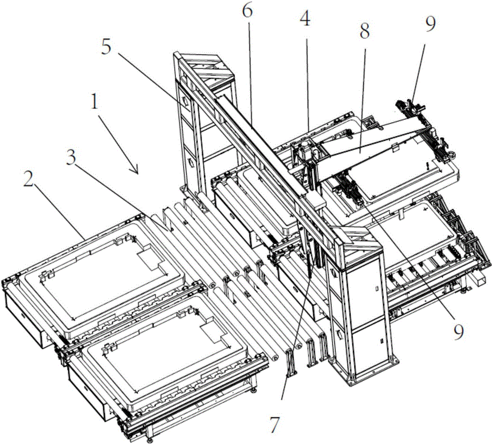
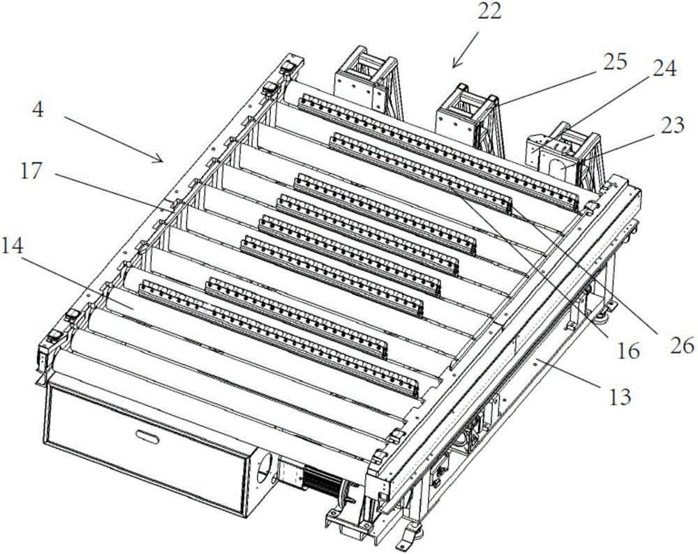
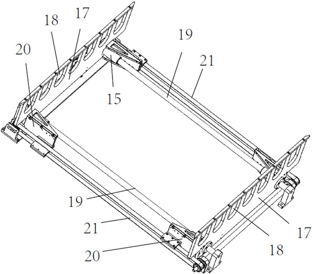
[0021] refer to Figure 1 to Figure 4 As shown, a self-positioning auxiliary code scanning mechanism includes a carrier conveying line 1, and the carrier conveying line includes a feed roller conveyor belt 2, a driven roller conveyor 3 and a positioning roller conveyor belt 4 arranged in sequence, and the carrier conveying line A gantry 5 is arranged above, and a sliding main beam 6 moving along the X-axis direction is arranged on the gantry, a sliding sub-beam 7 m...


PUM


Abstract

The invention discloses a self-positioning auxiliary code scanning mechanism. The mechanism comprises a carrier conveying line, and the carrier conveying line comprises a feeding roller way conveying belt, a driven roller way conveying belt and a positioning roller way conveying belt which are sequentially arranged; a portal frame is arranged above the carrier conveying line, a sliding main beam moving in the X-axis direction is arranged on the portal frame, and a sliding auxiliary beam which moves in the Z-axis direction is arranged on the sliding main beam; a supporting mounting plate is arranged on the sliding auxiliary beam, two detection beams moving in the Y-axis direction are arranged at the bottom of the supporting mounting plate, two mounting supports moving in the X-axis direction are arranged on the detection beams, and each mounting support is provided with a suction cup and a code scanning camera. Automatic film tearing and identifying can be achieved, the speed is high, and no damage exists.

Description

technical field [0001] The invention relates to the technical field of identification, in particular to a self-positioning auxiliary code scanning mechanism. Background technique [0002] Before many large-scale products are put into storage or used, because the external carrier packaging is the same, they need to be sorted and identified. Currently, manual operations are generally used. However, due to the high stacking of products, there is great inconvenience, and the product surface It has a layer of protective film, which needs to be torn to find information on the identification code on the surface, which is extremely inconvenient, and it is difficult to tear the film manually, and it is easy to damage the surface of the product. Contents of the invention [0003] The purpose of the present invention is to overcome the above problems in the prior art, and provide a self-positioning auxiliary code scanning mechanism. The present invention can automatically tear off th...

Claims


Application Information

Patent Timeline
Patent Type & Authority Applications(China)
IPC IPC(8): B65G43/08
CPCB65G43/08B65G2203/041
Inventor 郑贵军杨金玉郑建明
Owner SUZHOU LANGKUN AUTOMATION EQUIP CO LTD
Learn More