
Dynamic track spike lamp under linkage control with intersection annunciator and control method of dynamic track spike lamp

A technology of linkage control and control method, which is applied in the field of traffic sign lights, can solve problems such as formation of linkage, lack of intersection signals, and inability to prompt pedestrians and vehicles, so as to avoid congestion, ensure pedestrian safety, and enhance boundary and control The effect of speed

Active Publication Date: 2016-11-23
SHANDONG JIAOTONG UNIV
View PDF4 Cites 17 Cited by
  • Summary
  • Abstract
  • Description
  • Claims
  • Application Information

AI Technical Summary

Problems solved by technology

However, most of the current road stud lights emit a single yellow light, and the lighting mode of the double-sided road stud is simple and synchronous flashing, and there is no linkage with the intersection signal when working; at the same time, the LEDs on both sides of the road stud The light flashes synchronously, and it can only be an early warning for vehicles or pedestrians in a single direction, and it cannot make the same spike provide traffic information reminders for pedestrians and vehicles at the same time.

Method used


Image

  • Dynamic track spike lamp under linkage control with intersection annunciator and control method of dynamic track spike lamp
  • Dynamic track spike lamp under linkage control with intersection annunciator and control method of dynamic track spike lamp
  • Dynamic track spike lamp under linkage control with intersection annunciator and control method of dynamic track spike lamp

Examples


Embodiment Construction

[0033] The specific implementation manners of the present invention will be further described in detail below in conjunction with the accompanying drawings and embodiments.

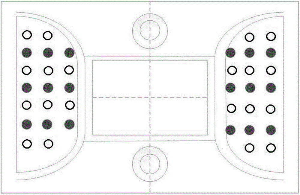
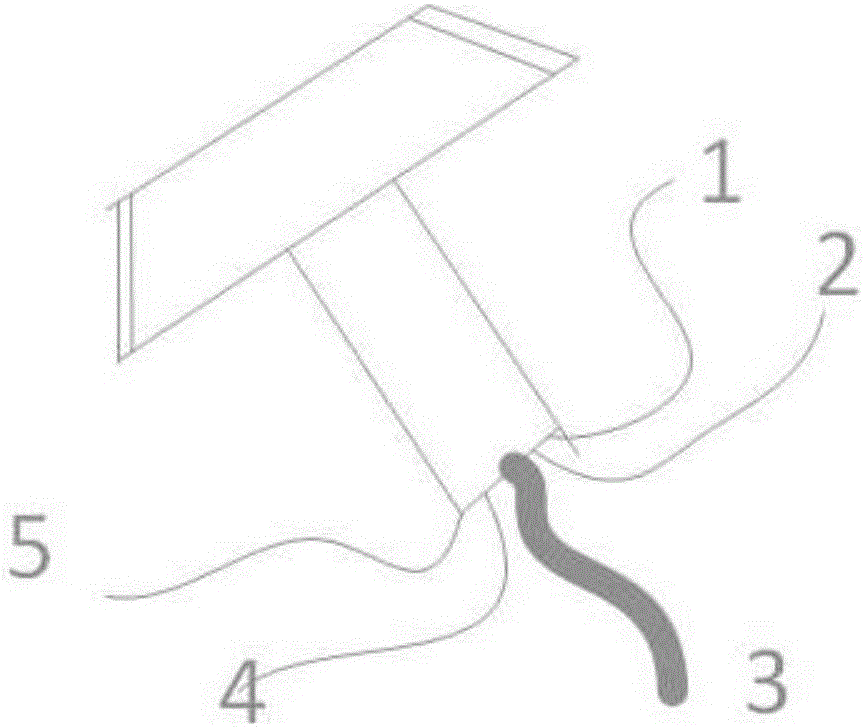
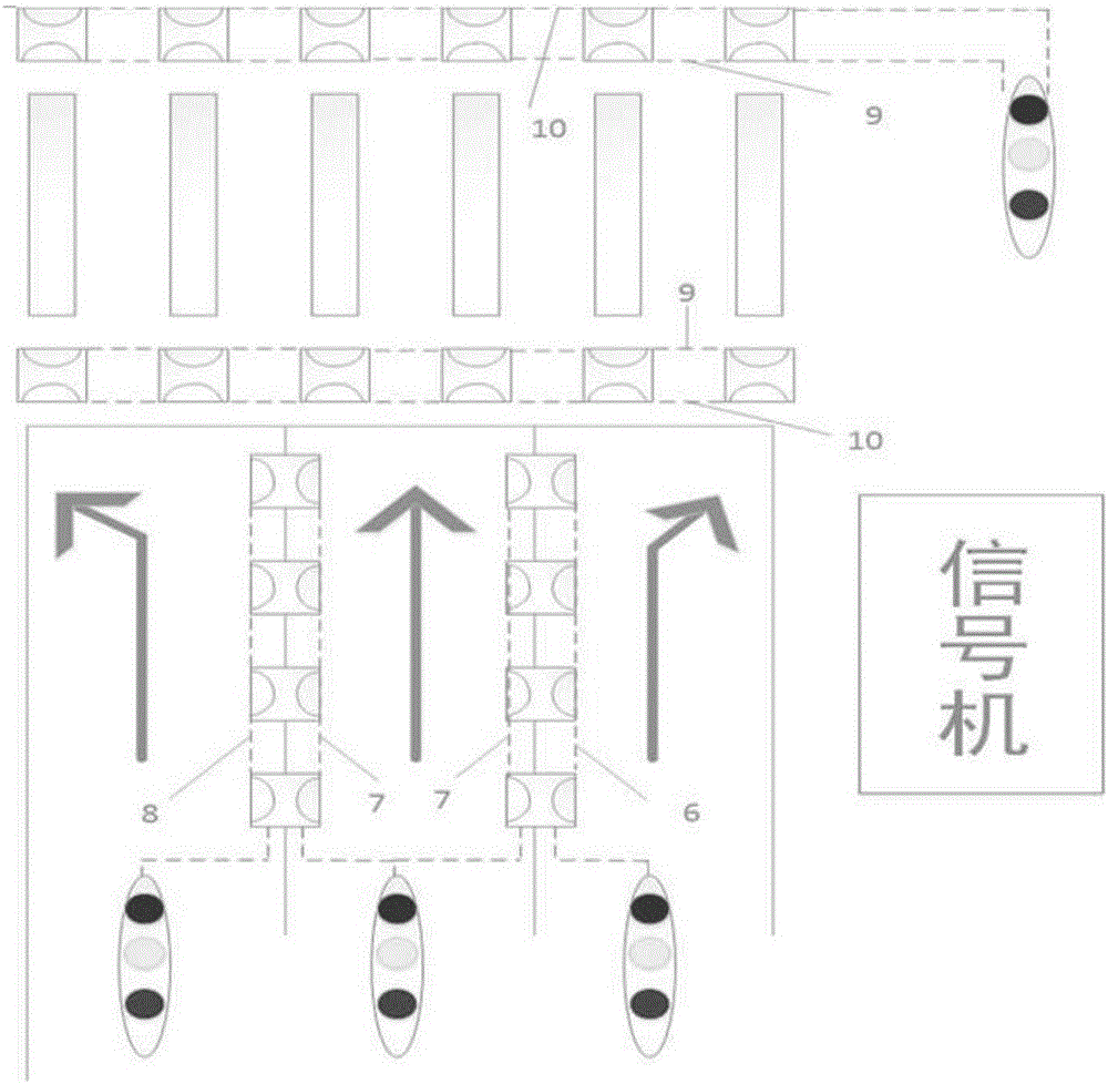
[0034] like figure 1 and figure 2 As shown in the figure, a dynamic road stud light controlled in conjunction with an intersection signal machine includes: a row of double-sided light-emitting road stud lights at a set distance; each light-emitting side includes alternately arranged red LED lights and green LED lights; The LED light and the green LED light are respectively connected to the single-chip microcomputer through their own control lines, and the single-chip microcomputer is connected to the traffic signal output port on the road adjacent to the road stud light controlled by the signal machine; lay them in a row on the lane dividing line or on the zebra crossing sides.

[0035] figure 1 There are three rows of green lights and four rows of red lights alternately arranged on the two sides of t...


PUM


Abstract

The invention discloses a dynamic track spike lamp under linkage control with an intersection annunciator and a control method of the dynamic track spike lamp. The dynamic track spike lamp comprises a column of double-face light-emitting track spike lamp bodies spaced at set intervals. Each light-emitting side face comprises red LED lamps and green LED lamps which are arranged alternately. The red LED lamps and the green LED lamps are connected with a single-chip microcomputer through control lines respectively. The track spike lamp bodies controlled by the single-chip microcomputer and the annunciator are connected with a traffic signal output port of an adjacent road. The double-face light-emitting track spike lamp bodies are laid on the two sides of a lane boundary line or zebra stripes. The dynamic track spike lamp has the beneficial effects that information of the annunciator can be displayed through the track spike lamp bodies, passing vehicles or pedestrians can judge whether to pass or not by observing track spikes on a road surface, and the situation that drivers and the pedestrians ignore observation of the lower road condition due to observation of the upper signal lamps when reaching an intersection is reduced.

Description

technical field [0001] The invention relates to the technical field of traffic sign lamps, in particular to a dynamic road stud lamp controlled in linkage with an intersection signal machine and a control method thereof. Background technique [0002] At present, with the continuous increase of vehicles, the facilities on the traffic roads are also constantly being constructed and optimized. In the face of large traffic volume and high speed, traffic sign markings play an important role in guiding and guiding. At night, the reflective lane line can be passively displayed under the illumination of the lights, but it cannot be displayed when it is a little farther away or when the lights are not illuminated, which brings inconvenience to vehicles driving on the road at night. At present, light-emitting road stud lights are installed at traffic intersections, entrances and exits with large traffic volumes, and multi-lane lanes to warn vehicles or pedestrians. [0003] Road stu...

Claims


Application Information

Patent Timeline
Patent Type & Authority Applications(China)
IPC IPC(8): E01F9/559G08G1/095
CPCG08G1/095
Inventor 张萌萌吴伟阳宋家恕
Owner SHANDONG JIAOTONG UNIV
Learn More