
Control method and device for continuous variable valve lift mechanism

A technology of valve lift and control method, applied in the field of control, can solve the problems of NVH performance decline, parts wear, strong impact of mechanical stop point and so on

Active Publication Date: 2016-11-23
GREAT WALL MOTOR CO LTD
View PDF6 Cites 2 Cited by
  • Summary
  • Abstract
  • Description
  • Claims
  • Application Information

AI Technical Summary

Problems solved by technology

However, in the process of adjusting the valve lift in the existing control method of the continuously variable valve lift mechanism, in order to realize the rapid adjustment of the valve, the limit surface of the mechanism often collides strongly with the mechanical stop point.
On the one hand, this will cause wear to the parts of the mechanism, resulting in a shortened service life of the mechanism, and the wear of the mechanism will in turn cause the position of the mechanical stop of the mechanism to shift, resulting in a decrease in the control accuracy of the mechanism by the ECU
On the other hand, the collision between the limit surface of the mechanism and the mechanical stop will also cause serious problems with the noise, vibration, harshness (NVH) of the mechanism and reduce the NVH performance

Method used


Image

  • Control method and device for continuous variable valve lift mechanism
  • Control method and device for continuous variable valve lift mechanism
  • Control method and device for continuous variable valve lift mechanism

Examples


Embodiment Construction

[0064] It should be noted that, in the case of no conflict, the embodiments of the present invention and the features in the embodiments can be combined with each other.

[0065] In addition, in order to clearly describe the technical solutions of the embodiments of the present invention, in the embodiments of the present invention, words such as "first" and "second" are used to distinguish the same or similar items with basically the same function and effect, Those skilled in the art can understand that words such as "first" and "second" do not limit the quantity and execution order.

[0066] The present invention will be described in detail below with reference to the accompanying drawings and examples.

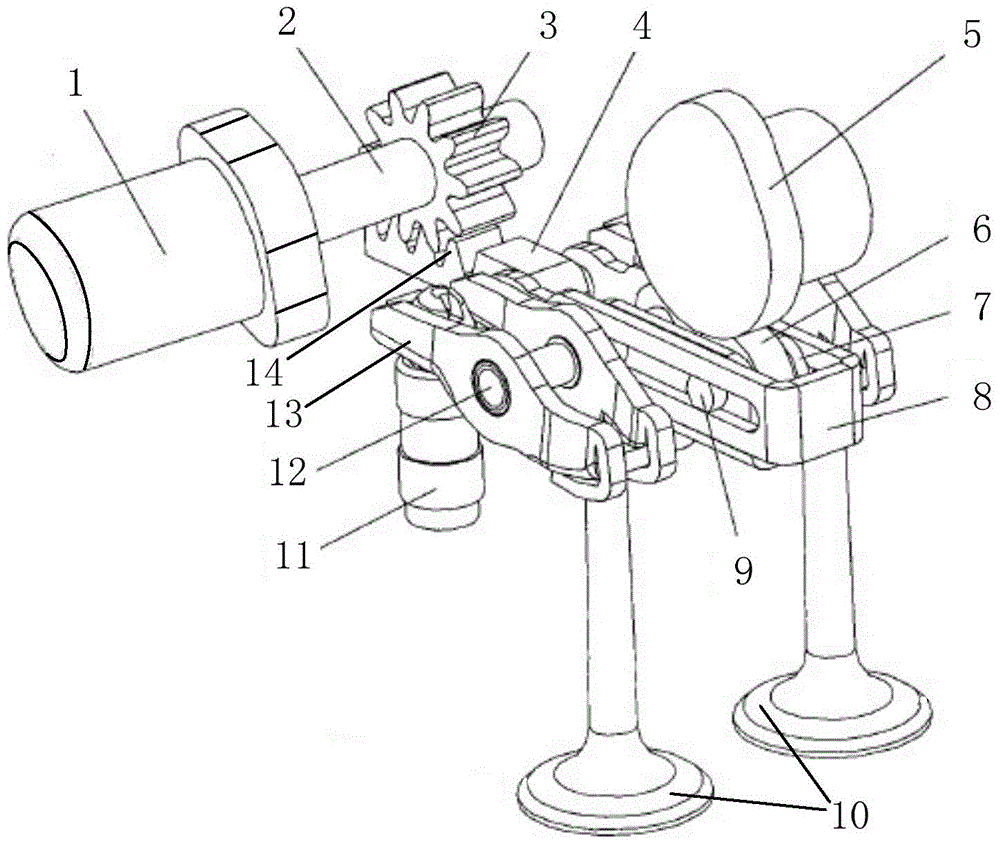
[0067] An exemplary structure of the continuously variable valve lift mechanism in this embodiment is as follows figure 1 As shown, it includes a cam 5, and the cam 5 is connected with the roller 7 in the first rocker arm 6. One end of the first rocker arm 6 is connected t...


PUM


Abstract

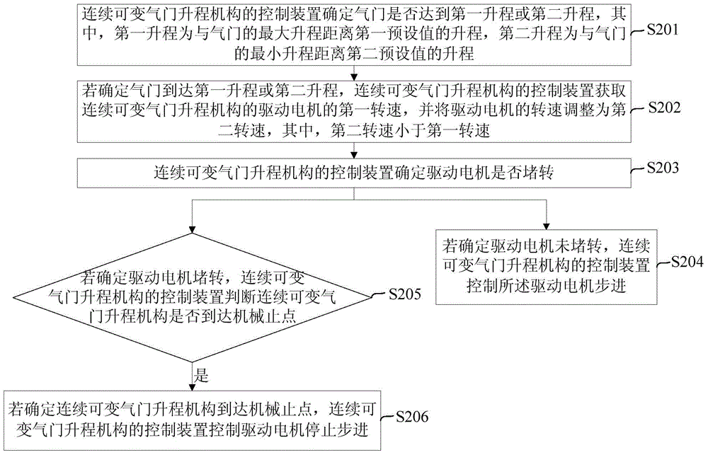
The invention provides a control method and device for a continuous variable valve lift mechanism. According to the control method and device, it can be avoided that a limiting face of the mechanism fiercely impacts on a mechanical dead point, and therefore abrasion of parts of the mechanism is reduced, the control precision of the mechanism is ensured, and the sound quality of an engine is improved. The method includes the steps that whether a valve reaches the first lift or the second lift is confirmed, wherein the first lift is the lift which is the difference between the maximum lift of the valve and a first preset value, and the second lift is the lift which is the difference between the minimum lift of the valve and a second preset value; and if it is confirmed that the air valve reaches the first lift or the second lift, the first rotating speed of a drive motor of the continuous variable valve lift mechanism is obtained and adjusted to be the second rotating speed, wherein the second rotating speed is smaller than the first rotating speed. The control method and device are suitable for the technical field of control.

Description

technical field [0001] The invention relates to the technical field of control, in particular to a control method and device for a continuously variable valve lift mechanism. Background technique [0002] The continuously variable valve lift mechanism can make the valve lift continuously change within a certain range, so compared with the conventional variable valve lift mechanism, it can control the intake air volume of the engine more flexibly, and can effectively reduce the partial load Reduced pumping losses for improved fuel economy. [0003] Due to the complex structure of the continuously variable valve lift mechanism, the electronic control unit (Electronic Control Unit, ECU) needs to be based on high mechanism control accuracy and intake air measurement accuracy to achieve accurate control of the valve lift. However, in the process of adjusting the valve lift in the existing control method of the continuously variable valve lift mechanism, in order to realize the r...

Claims


Application Information

Patent Timeline
IPC IPC(8): F01L1/34
Inventor 冯柏超徐黎明李冠宇陈超胡佳佳尹吉张文龙刘涛刘胜强房艳龙
Owner GREAT WALL MOTOR CO LTD
Learn More