Full-active cooling hypersonic flight vehicle

A hypersonic and active cooling technology, which is applied to aircraft parts, aircraft control, and air flow affecting the surface of the aircraft, can solve the problems of non-metal composite material pollution, bump damage, moisture absorption deformation, etc. Use requirements, ensure control accuracy, and reduce the effect of flight resistance

Active Publication Date: 2018-04-17
BEIJING LINJIN SPACE AIRCRAFT SYST ENG INST +1
View PDF8 Cites 19 Cited by
  • Summary
  • Abstract
  • Description
  • Claims
  • Application Information

AI Technical Summary

Problems solved by technology

The tip of the aircraft, the rudder, and the leading edge of the wing, as the key aerodynamic shape parts of the aircraft, are ablated and receded or deformed, which will reduce the flight control accuracy of the aircraft, and the aircraft with aerodynamic shape ablated and deformed cannot be reused
[0006] (3) Due to the limitation of the thermal environment adaptability of the application of anti-insulation materials, the flight trajectory of traditional passive thermal protection hypersonic vehicles is relatively fixed, so the scope of application of its combat missions is also narrow
[0007] (4) Compared with metal materials, traditional non-metallic anti-insulation products are easy to absorb moisture and deform, and the products are not conducive to long-term storage, and the mechanical properties of non-metallic anti-insulation materials are low, and they are prone to bumps during hoisting and transportation destroy
[0008] (5) Most non-metallic composite materials are polluted during the production and testing process, especially during the thermal test process, the incomplete combustion of non-metallic materials produces harmful gases that cause serious pollution to the environment

Method used

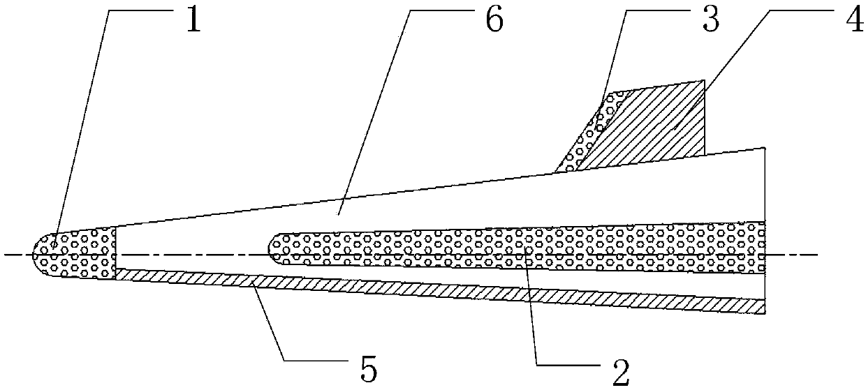
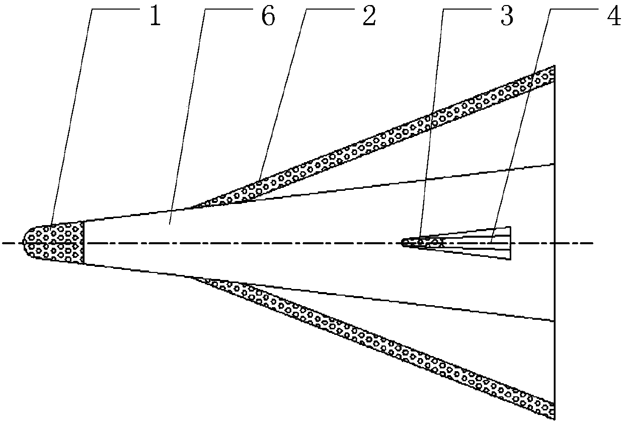

Image

  • Full-active cooling hypersonic flight vehicle
  • Full-active cooling hypersonic flight vehicle
  • Full-active cooling hypersonic flight vehicle

Examples


Embodiment Construction

[0030] The present invention will be further described in detail below in conjunction with the accompanying drawings and specific embodiments.

[0031] A fully active cooling hypersonic aircraft of the present invention is characterized in that it comprises: sweating cooling end, sweating cooling wing leading edge, sweating cooling rudder leading edge, regenerative cooling rudder surface, regenerative cooling windward side, aircraft leeward side; sweating cooling end The head, the leading edge of the sweat cooling wing and the leading edge of the sweat cooling rudder are equipped with a porous structure, and a liquid cooling medium is stored inside. The liquid cooling medium can be supplied from the porous structure and flow through the porous structure for heat exchange. The gaseous form flows out of the outer surface of the terminal; the regenerative cooling method is used to cool the rudder surface and the windward surface of the aircraft respectively, and the liquid cooling...


PUM


Abstract

The invention discloses a full-active cooling hypersonic flight vehicle which comprises a transpiration cooling end, a transpiration cooling wing front edge, a transpiration cooling rudder front edge,a regenerative cooling rudder surface, a regenerative cooling windward side and a flight vehicle leeside, wherein porous structures are formed in the transpiration cooling end, the transpiration cooling wing front edge and the transpiration cooling rudder front edge, and the interiors of the porous structures are filled with liquid cooling media; the liquid cooling media can be supplied outwardsfrom the porous structures, flow through the porous structures to perform heat exchange, are heated and then flow out of the outer surface of the end in a gaseous form; and the regenerative cooling rudder surface and the regenerative cooling windward side are respectively used for cooling the rudder surface and the windward side of the flight vehicle in a regenerative cooling manner, and the liquid cooling media carried inside the flight vehicle are used for blocking, cooling and taking away pneumatic heating volume of the flight vehicle transferred into the flight vehicle in the hypersonic flight process, so that thermal protection requirements of the flight vehicle on high-speed, long-term and long-distance flight in the atmosphere are met.

Description

technical field [0001] The invention relates to a fully active cooling hypersonic aircraft, in particular to a novel thermal protection mode hypersonic aircraft structure, which belongs to the technical field of hypersonic aircraft. Background technique [0002] When the aircraft flies in the atmosphere at hypersonic speed, the air around the aircraft is subjected to strong compression and severe friction, and the temperature of the air rises and is transmitted to the surface of the aircraft. This phenomenon is called aerodynamic heating. As the flight Mach number increases, the aerodynamic heating becomes more serious, especially the tip, wing, rudder leading edge and other parts of the hypersonic vehicle are the most severely aerodynamic heating parts, the highest heat flow can reach 20-30MW / m2, the surface The temperature can reach above 3000℃. In order to protect hypersonic aircraft (greater than 5 times the speed of sound) from being damaged by the high temperature gen...

Claims


Application Information

Patent Timeline
Patent Type & Authority Applications(China)
IPC IPC(8): B64C1/40B64C21/02
CPCB64C1/40B64C21/02B64C2230/16
Inventor 高翔宇尘军王振峰白光辉檀妹静
Owner BEIJING LINJIN SPACE AIRCRAFT SYST ENG INST
Why Eureka
Try Eureka