
Integrated draught fan assembly

An integrated fan technology, applied to liquid fuel engines, pump components, components of pumping devices for elastic fluids, etc., can solve problems such as personal safety accidents, reduce material costs, eliminate potential safety hazards, and improve labor costs. The effect of production efficiency

Active Publication Date: 2016-11-23
HAIER SMART HOME CO LTD
View PDF5 Cites 1 Cited by
  • Summary
  • Abstract
  • Description
  • Claims
  • Application Information

AI Technical Summary

Problems solved by technology

[0003] But as far as the current design method is concerned, there are the following problems: 1. The fan wires used to control the operation of the fan (that is, the wires connected to the fan) are often placed directly inside the fan box after simple bundling, that is, the fan and the fan wire It is enclosed in the same space, so there is a hidden danger of the fan winding the fan line during the operation of the fan, which may cause personal safety accidents in severe cases; 2. The fan box is generally formed by injection molding, etc., because the box body and box of the traditional fan box Cover separation design, a complete fan box requires at least two sets of different molds to complete

Method used


Image

  • Integrated draught fan assembly
  • Integrated draught fan assembly
  • Integrated draught fan assembly

Examples


Embodiment Construction

[0033] The present invention will be described in detail below in conjunction with various embodiments shown in the accompanying drawings. Figure 1 to Figure 9 As shown, it is some preferred embodiments of the present invention.

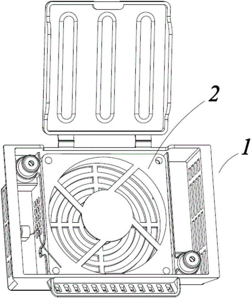
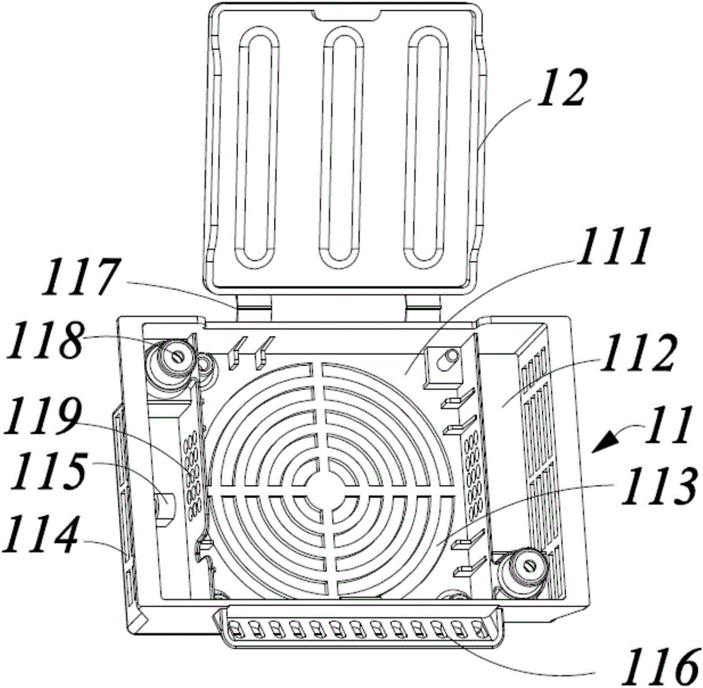
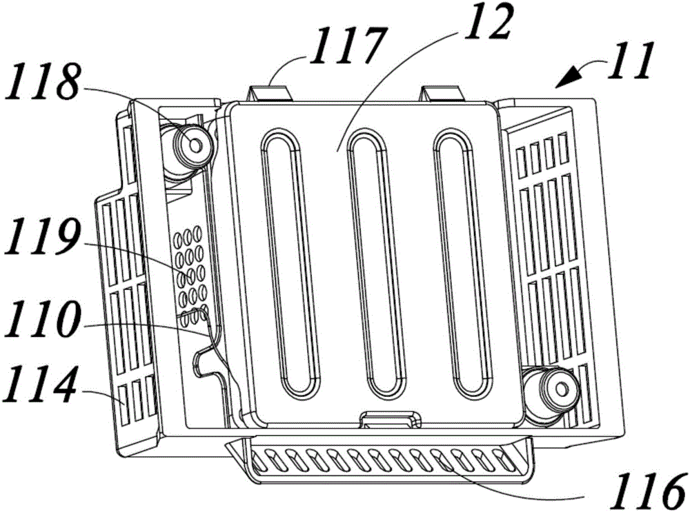
[0034] figure 1 Shown is a three-dimensional schematic diagram of an embodiment of the integrated fan assembly of the present invention in an uncovered state, figure 2 It is a three-dimensional schematic diagram of the fan box (without fan) when it is not covered, image 3 The three-dimensional schematic diagram of the integrated fan assembly under the cover state, Figure 4 The top view of the one-piece fan assembly with the cover closed, Figure 5 Side view of the one-piece fan assembly with the cover closed.

[0035] As shown in the figure, the integrated fan assembly of the present invention includes an integrated fan box 1 and a fan 2, wherein the integrated fan box 1 includes a box body 11 and a box cover 12 arranged on the box body 11; t...


PUM


Abstract

The invention discloses an integrated draught fan assembly. The integrated draught fan assembly comprises an integrated draught fan box and a draught fan. The integrated draught fan box comprises a box body and a box cover arranged on the box body. The box body is provided with a draught fan holding tank and box body side tanks arranged on two sides of the draught fan holding tank. Through the reasonable design of an integrated structure, when the box cover of the integrated draught fan assembly covers the bottom of the draught fan holding tank in an overturned mode, and clamping of a draught fan line is formed between the box cover and the box body. An effective solution is provided for separating the draught fan and the draught fan line in a refrigerator, and the problem of draught fan winding is solved. Through the design method of integration, the mould quantity of the draught fan box manufacturing is effectively reduced, and product cost is reduced.

Description

technical field [0001] The invention relates to a device for circulating cold air inside a refrigerator, in particular to an integrated fan assembly, which belongs to the field of household appliances. Background technique [0002] At present, the fan-equipped refrigerators on the market are composed of two parts: the fan box and the fan. The fan box includes a box body and a box cover with a separate design. The box cover can be closed on the box body. To form a state of containing the fan. [0003] But as far as the current design method is concerned, there are the following problems: 1. The fan wires used to control the operation of the fan (that is, the wires connected to the fan) are often placed directly inside the fan box after simple bundling, that is, the fan and the fan wire It is enclosed in the same space, so there is a hidden danger of the fan winding the fan line during the operation of the fan, which may cause personal safety accidents in severe cases; 2. The...

Claims


Application Information

Patent Timeline
Patent Type & Authority Applications(China)
IPC IPC(8): F04D29/40F04D29/60F25D17/06
CPCF04D29/403F04D29/601F25D17/062
Inventor 姜岩卢晓东任宪伟郭磊
Owner HAIER SMART HOME CO LTD
Learn More