External pressure universal expansion joint

An expansion joint, horizontal type technology, applied in the field of expansion joints, can solve the problems of inconvenience in production and residents' life, leakage of corrugated pipes, water interruption and maintenance, etc., and achieve the effect of preventing excessive stretching, avoiding load-bearing deformation, and ensuring overall stability.

Active Publication Date: 2016-11-23
CHENGUANGDONGLUO BELLOWS CO LTD NANJING
View PDF8 Cites 4 Cited by
  • Summary
  • Abstract
  • Description
  • Claims
  • Application Information

AI Technical Summary

Problems solved by technology

The expansion joints used to absorb the lateral displacement are usually internal pressure transverse metal expansion joints. Under high pressure conditions, the internal pressure transverse expansion joints in the prior art will suffer from column instability due to the large amount of lateral compensation required. In addition, the corrugated pipe may leak due to corrosion, fatigue and other reasons. Once a leak occurs, the central heating pipeline will suddenly stop running, and it will be necessary to stop the gas and water for maintenance, which will bring harm to production and residents’ lives. great inconvenience

Method used


Image

  • External pressure universal expansion joint
  • External pressure universal expansion joint

Examples


Embodiment Construction

[0016] The present invention will be further described below in conjunction with the accompanying drawings.

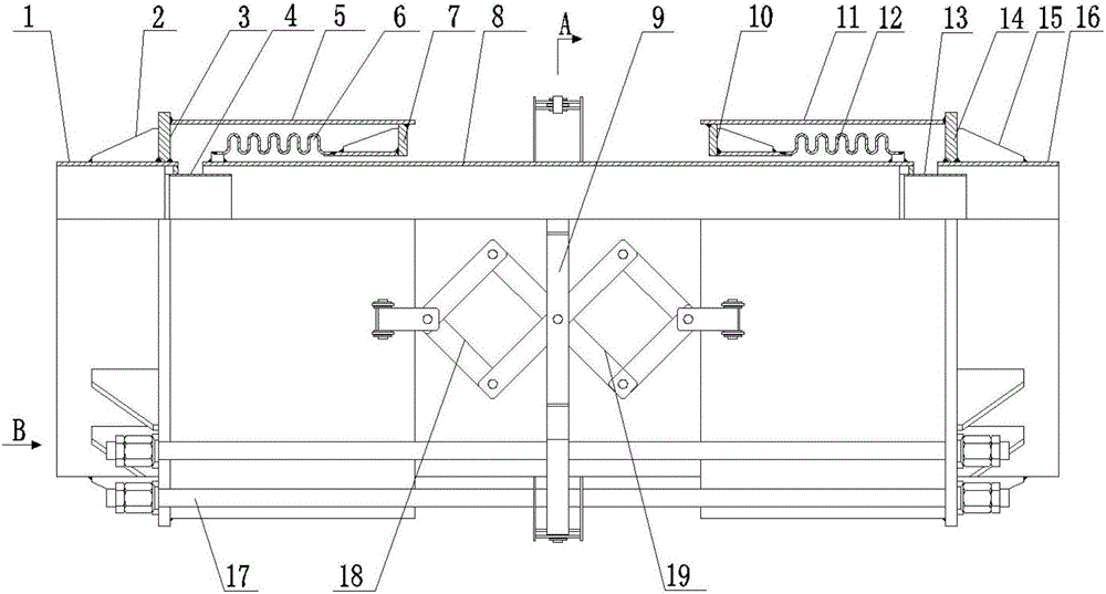
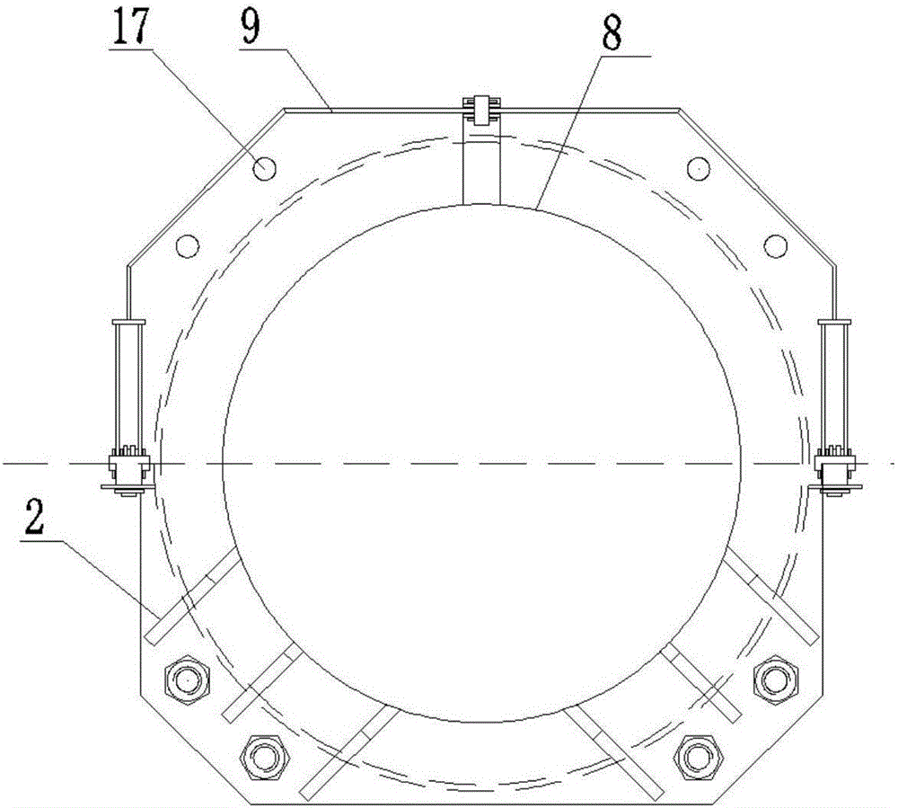
[0017] Such as figure 1 , figure 2 The external pressure transverse expansion joint shown includes a left connecting pipe 1 and a right connecting pipe 16, the left connecting pipe 1 is connected to the left outer casing 5, the left outer casing 5 is coaxially fitted with a left bellows 6, and the left outer casing 5 is connected to the left outer casing 5. The bellows 6 is connected at the end through the left pressure ring plate 7; the right connecting pipe 16 is connected with the right outer casing 11, and the right outer casing 11 is coaxially fitted with the right bellows 12, and the right connecting pipe 16 and the right bellows 12 pass through at the end The right pressure-bearing ring plate 10 is connected; it also includes an intermediate connecting pipe 8 arranged in the left bellows 6 and the right bellows 12, and the two ends of the intermediate connecti...


PUM


Abstract

The invention discloses an external pressure universal expansion joint. The external pressure universal expansion joint comprises a left connecting pipe and a right connecting pipe, wherein the left connecting pipe is connected with a left outer sleeve, a left corrugated pipe is arranged in the left outer sleeve, and the left outer sleeve and the left corrugated pipe are connected through a left pressure bearing annular plate at one end of the left outer sleeve and the corresponding end of the left corrugated pipe; and the right connecting pipe is connected with a right outer sleeve, a right corrugated pipe is arranged in the right outer sleeve, and the right connecting pipe and the right corrugated pipe are connected through a right pressure bearing annular plate at one end of the right connecting pipe and the corresponding end of the right corrugated pipe. The external pressure universal expansion joint further comprises a middle connecting pipe arranged in the left corrugated pipe and the right corrugated pipe, wherein one end of the middle connecting pipe is connected with the other end of the left corrugated pipe, the other end of the middle connecting pipe is connected with the other end of the right corrugated pipe, a left lining tube is arranged in the left outer sleeve, the free end of the left lining tube is arranged inside the left corrugated pipe, a right lining tube is arranged inside the end, located on the right corrugated pipe, of the middle connecting pipe, and the free end of the right lining tube is arranged in the right connecting pipe. According to the external pressure universal expansion joint, the structure that two groups of external pressure type multi-layer U-shaped corrugated pipes are combined is adopted, the problem of column instability is avoided, and therefore, the external pressure universal expansion joint has the high horizontal compensation capacity under the working conditions of high pressure and high temperature, and can meet the requirement on the compensation capacity of an on-site long-range pipeline.

Description

technical field [0001] The invention relates to the field of expansion joints, in particular to an external pressure transverse expansion joint. Background technique [0002] The urban central heating project has always been a national key livelihood project related to the people's personal life. With the continuous increase of the social population and the development needs of the national economy, the demand for heating is increasing year by year. High-pressure, large-diameter large-scale central heating Pipelines emerged as the times require, and then higher requirements were put forward for the lateral compensation capability of expansion joints used in heating pipelines. The expansion joints used to absorb the lateral displacement are usually internal pressure transverse metal expansion joints. Under high pressure conditions, the internal pressure transverse expansion joints in the prior art will suffer from column instability due to the large amount of lateral compensa...

Claims


Application Information

Patent Timeline
Patent Type & Authority Applications(China)
IPC IPC(8): F16L51/03
CPCF16L51/025F16L51/028F16L51/03
Inventor 梁薇牛玉华王文刚
Owner CHENGUANGDONGLUO BELLOWS CO LTD NANJING
Why Eureka
Try Eureka